Wiring harness design in CATIA V5 - 3D modeling Week 7 Challenge
Q1. Flatten the harness assembly completed in “ week 4 challenge”. Place the flattened view on drawing sheet. Ensure bundles with protective coverings has different visuals on drawing view.
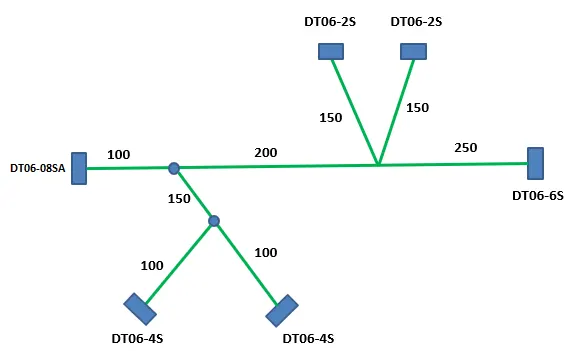
Answer:
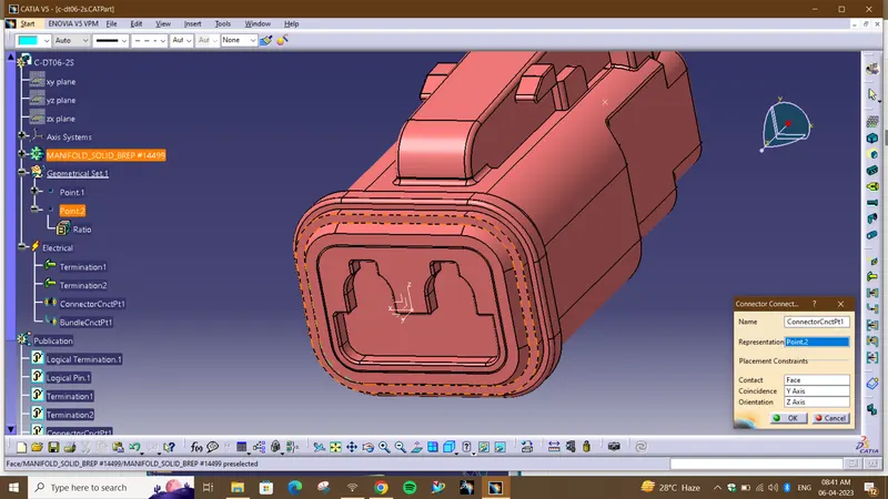
1.DT06-2S
- Create midpoint on the contact face which will be normal to wire bunddle insertion.
- Craete Axis System with respect to the point which we have created and defining the axis direction.
Switch to 'Electric Part Design'
- Define the part as connector in catia, give no. of termination as 2 because we have 2 entry points for wire.
- Bundle connection point:
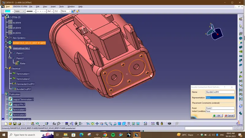
- Connector connection point:
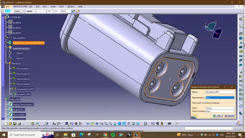
2. DT06-4S
- Create midpoint on the contact face which will be normal to wire bunddle insertion.
- Craete Axis System with respect to the point which we have created and defining the axis direction.
Switch to 'Electric Part Design'
- Define the part as connector in catia, give no. of termination as 4 because we have 4 entry points for wire.
- Define Bundle connection point
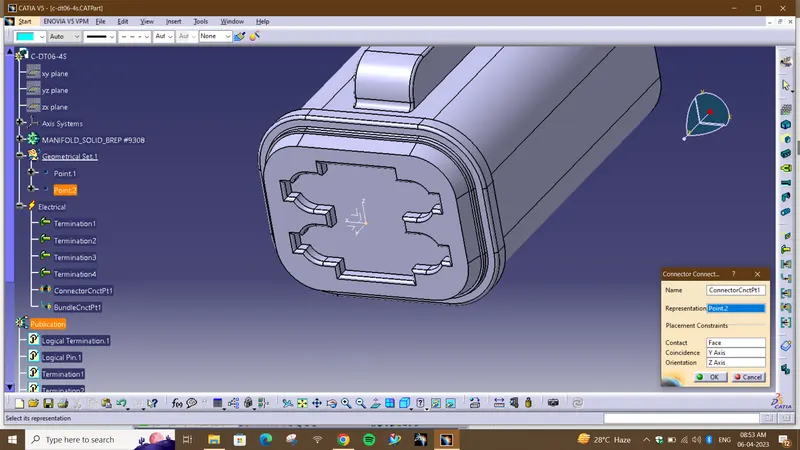
- Define connector connection point
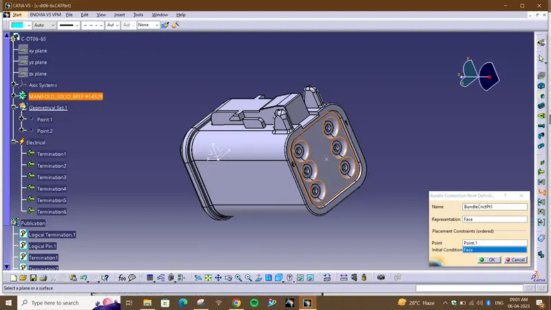
3.DT06-6S
- Create midpoint on the contact face which will be normal to wire bunddle insertion.
- Craete Axis System with respect to the point which we have created and defining the axis direction .
Switch to 'Electric Part Design'
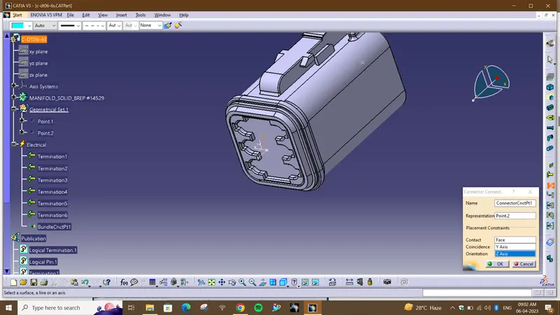
- Define the part as connector in catia, give no. of termination as 6 because we have 6 entry points for wire.
- Define Bundle connection point:
- Define connector connection point
4.DT06-08SA
- Create midpoint on the contact face which will be normal to wire bunddle insertion.
- Craete Axis System with respect to the point which we have created and defining the axis direction as shown below.
Switch to 'Electric Part Design'
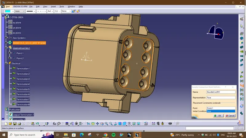
- Define the part as connector in catia, give no. of termination as 8 because we have 8 entry points for wire.
- Define Bundle connection point:
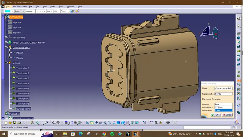
- Define connector connection point:
Product
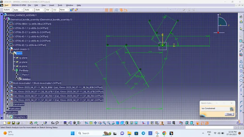
- Open a new product file and imported all the defined models into it.
- Draw a sketch as required.
- Using snap arranging the Connectors by following the Layout.
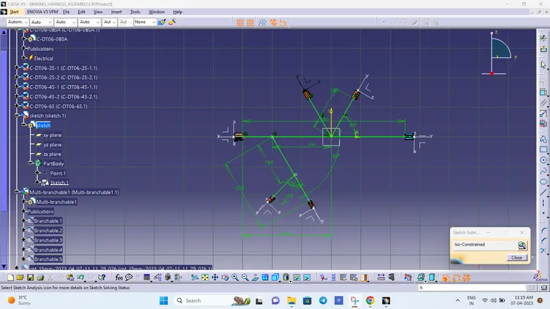
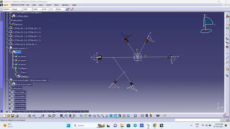
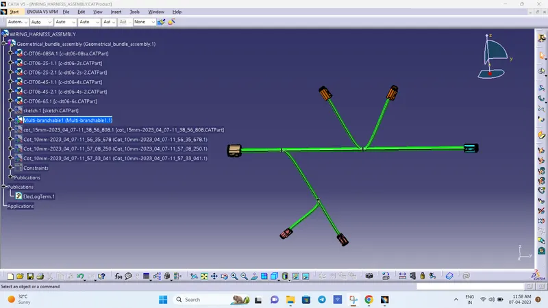
Creating Multi-Branching to the connectors
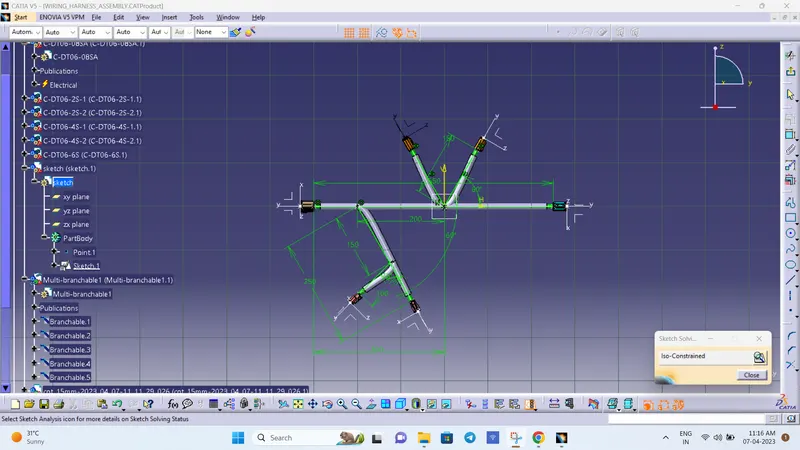
creating a protective covering
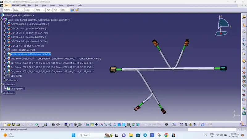
Harness Flattening Procedure:
- Harness flattening can be created from the Electrical Harness Flattening Workbench in CATIA V5.
- Create a new product file in the Electrical Harness Flattening workbench and rename it as of our requirement.
- Select the product file and define Flattening parameters to it. And we can rename it as of our requirement.
- Save the flattening product file in the save folder which is having all the other required documents.
- Create vertical windows with Harness assembly product and flattening product files.
- Using the Extract option, extract the harness assembly into the flattening product.
- Convert the extracted harness assembly into the flattened harness assembly by using the Flatten commend.
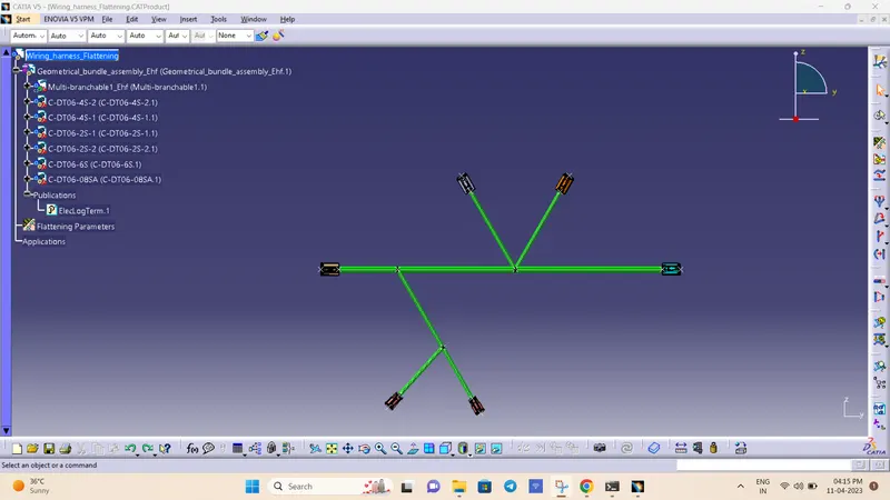
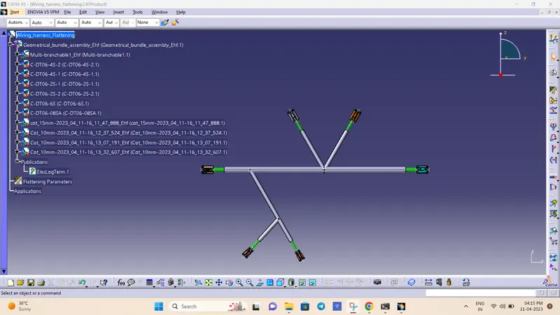
Create a Drawing File for the flattened harness product.
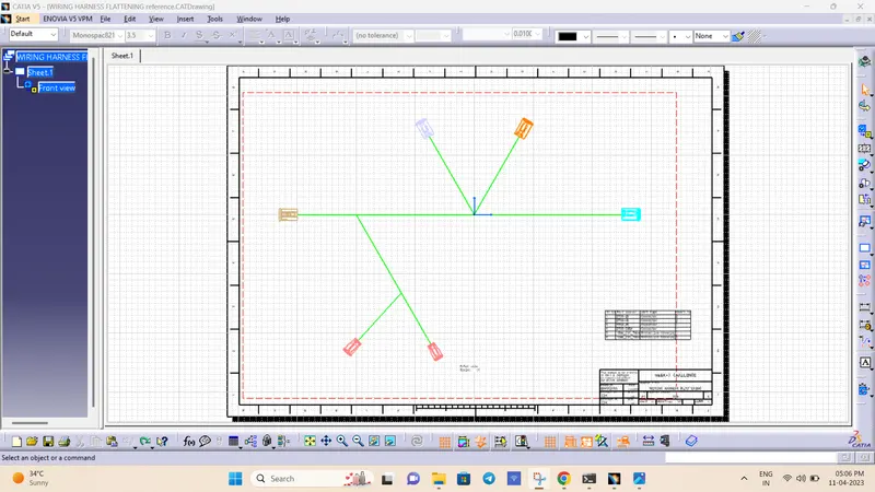
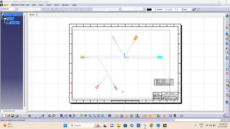
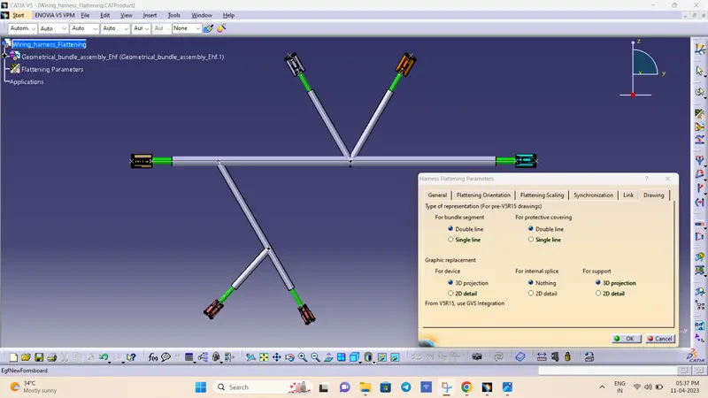
- First, we need to make sure that in the flatten parameter settings bundles and protective coverings have different graphical representation which are,
Bundle Segments – Single line representation
Protective coverings – Double line representation.
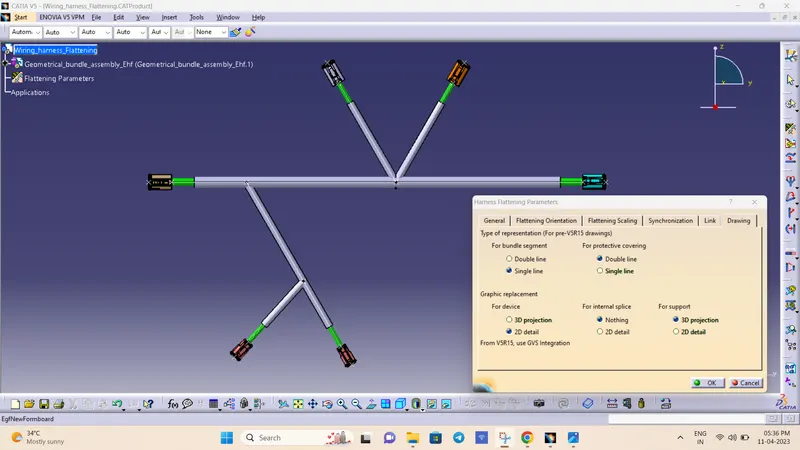
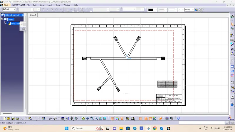
Drawing without protective covering
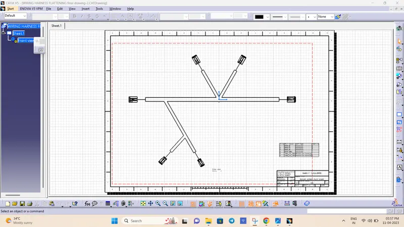
Drawing with protective covering
Bundle Segments - Double line representation
Protective coverings – Double line representation.
Drawing without protective covering:
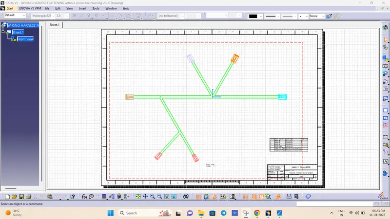
Drawing with protective covering
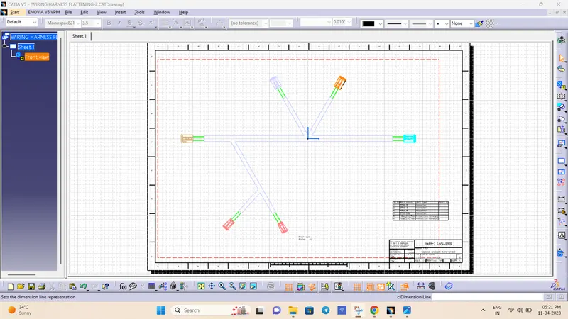
Final Drawings: