Wiring harness design in CATIA V5 - 3D modeling Week 7 Challenge
Q.1] Flatten the harness assembly completed in “ week 4 challenge”. Place the flattened view on drawing sheet. Ensure bundles with protective coverings has different visuals on drawing view.
In this project, we will going to flatten the harness assembly which was completed in "Week-4 Challenge". And then placed the flattened view on dawing sheet.
i) Flatten the hrness assembly
First we want to create a product file and then navigate to the 'Electrical Harness Flattening' and save it on same location in the wiring harness assembly. And before importing the harness assembly we want to set the flattening parameters which required to flatten the harness assembly by using the harness flattening parameters tool.
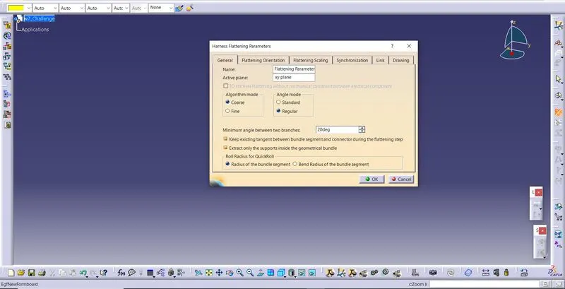
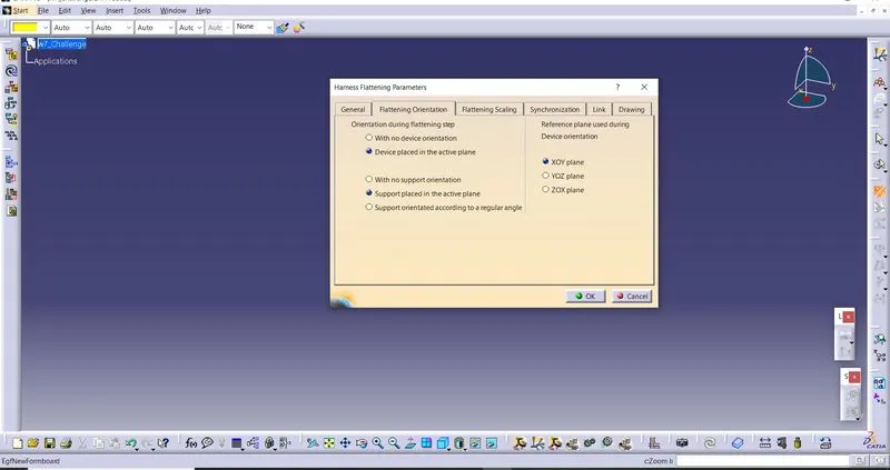
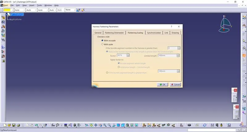
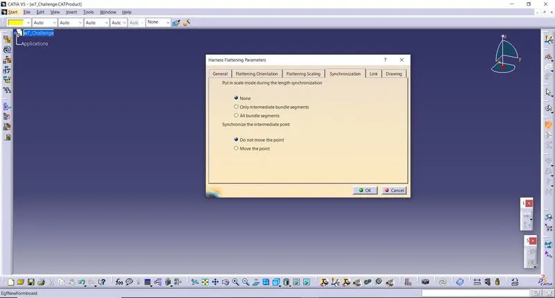
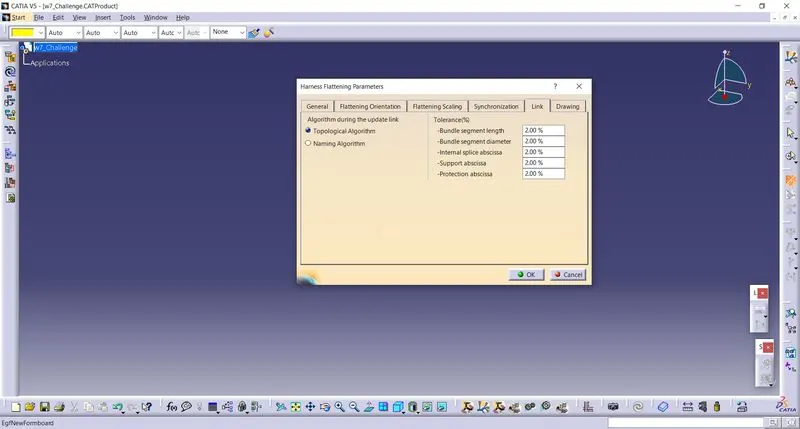
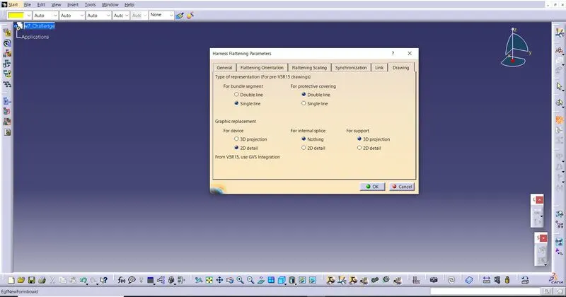
While defining the harness flattening parameters in the drawing menu single line is selected for bundle segment and double line is selected for protective coverings in order to differentiate between the wire bundle and cot tubes in drafting.
And then by selecting the 'Extract' option in the electrical harness flattening then by using the window option we can select the harness assembly product (W4-Challenge). When we click on it, it will import to the Wiring harness flattening assembly workbench of the product file.
We can see that our new harness assembly file is imported to our product by using the "EHF" extension.
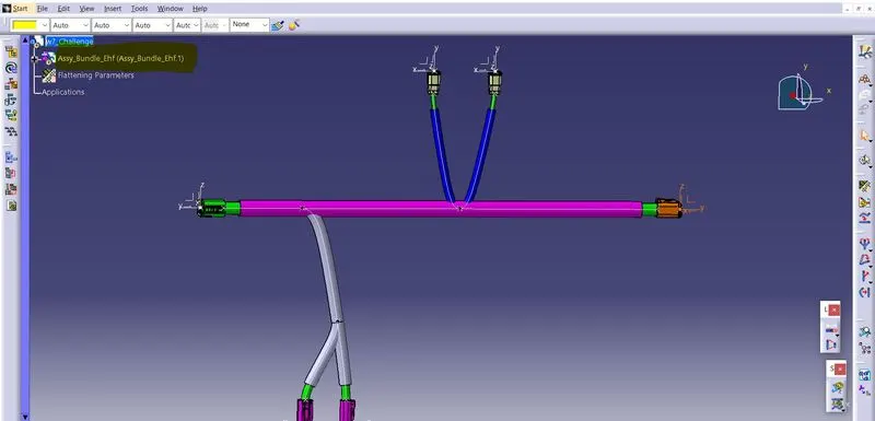
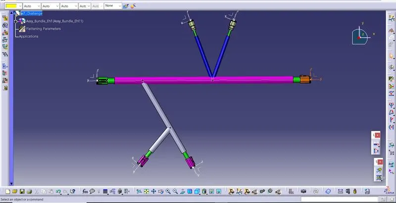
And then select the flatten option then select the active plane for flatten in that specific plane side. And then select any one of the branch then select all the branches. All branches are selected only when all the bundle segments are fully connected. After all the bundles are selected press OK to flatten the assembly.
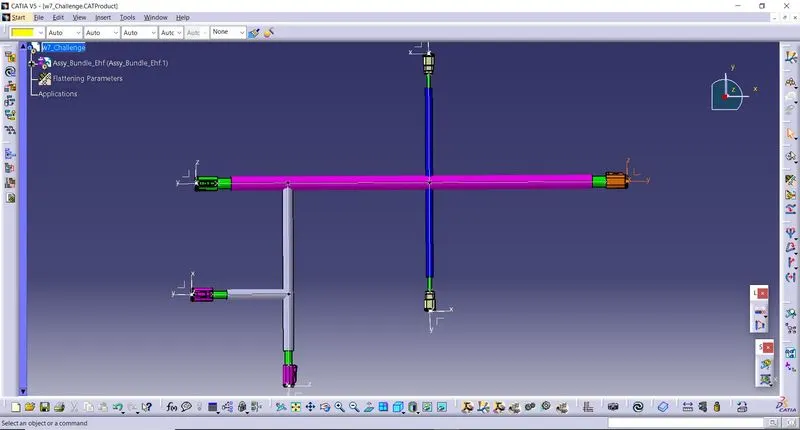
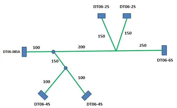
Use 'Rotate' and other commands to rotate the branches and bring them in proper orientation as per the given layout.
Drafting :
First we want open a new drawing file and then save it to the same location where the assembly harness files.
By selecting the front view option in the drawing then selecting any one of the flat faces of the connector and orient the view as per the requirement for adding the harness assembly diagram.
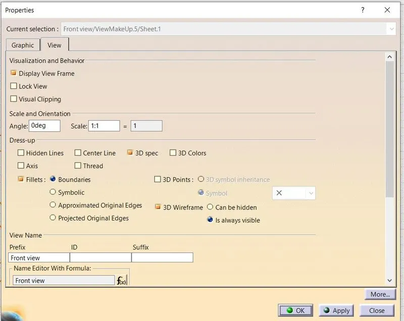
Then go to the properties of the view and select the '3D Wireframe' on and ' Is always visible' option in order to see properly the Wire bundle, connectors and the protection coverings.
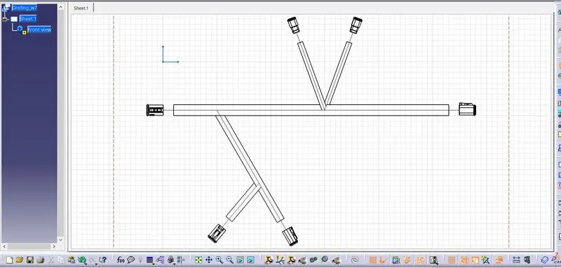
In this bundles are represented as single line and the protection coverings are represented as double lines.
Finally the given assembly flattened and then drafted.