Wiring harness design in CATIA V5 - 3D modeling Week 7 Challenge
Report on wire harness flattening and 2D drawing created out of it.
Aim:- Apply wire harness flatenning to the harness assembly then create the 2d drawing out of it.
Given:
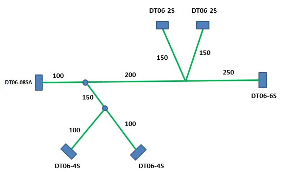
Step 1: Create a new product file naming it as flattening assembly, then open that file in electrical harness flattening.
- Now define the harness flatenning parameters by simply clicking on command available in workbench.
- There are few changes we done on the parameters such as mini. angle between two branches increased to 20 deg, and some changes are shown below:
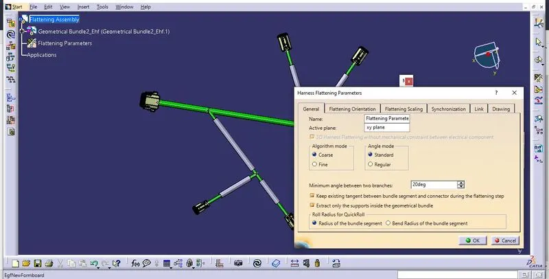
- AT the end by clicking okay our flattening parameters are defined for the product.
Step 2: Now add the harness assembly product by first opening it in the seperate window.
- By clicking on the window and Vertically tilt window we can open both the flattening product file and harness assembly together.
- Now clicking on the extract command in the flattening harness assembly and clicking on harness assembly we could place harness assembly into flattening product file.
- Now using the command flatten and selecting all branches we could flatten whole assembly as shown below:
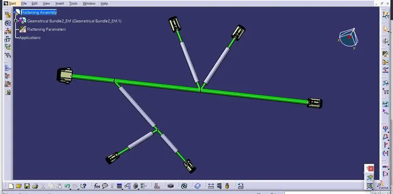
- Save this file in the same folder as that of harness assembly.
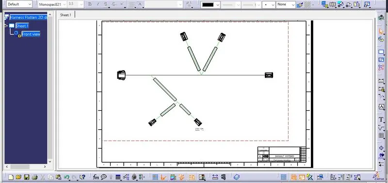
Step 3: Now create the new drawing file to represent this flattening assembly into 2D drawing.
- Take the front view of the assembly to represent on the sheet, and turn on the 3D wireframe to always visible on the sheet properties.
- Give different colour code to branches that have protective coverings such as green.
- And give frame and title box to drawing sheet in sheet background so our sheet will look like this:
-