Wiring harness design in CATIA V5 - 3D modeling Week 7 Challenge
Objectives:
- Define the mechanical parts electrically and the bundle flattening has to be done in the CATIA flattening workbech
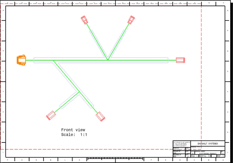
- 2D drawing of the bundle with connector representation and different colour coding for bundle with protective covering
Answer:
Define the mechanical connectors Electrically:
- First step is to create the parameters of the mechanical connectors using mechanical part workbench.
- Next step is to create bundle connection point and create connector connection point.
- Then create connector connection axis.
- Then define the connectors electrically using electrical part workbench, where define bundle connection point and connector connection point.
Bundle Routing:
- Initial step for creating bundle routing is arranging the connectors as per the layout location.
- Then add all the connectors in the geometrical bunde assembly file using existing file option or add using catalog browser option from part assembly workbench
- After arranging the connectors in the desired location the next step is to create routing.For creating routing we have to select multi branchable document option from electrical harness assembly work bench., Where we have to put the bundles in the connectors.
Add protective covering:
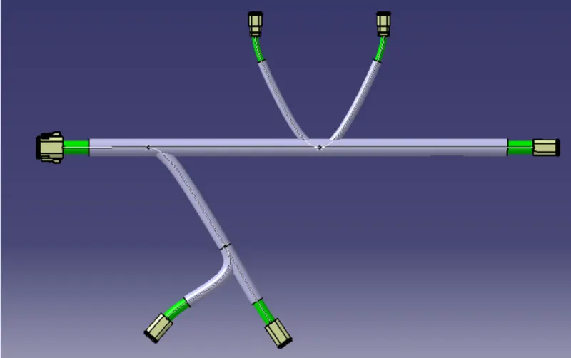
- After creating bundle of the connectors next step is to creating bundle protection corrogated tubes.
- For creating cot tubes in the bundle choose protective cover option and select the bundle segment for creating the cot tubes and choose the correct cot tubes from the catalog from the browse option, the put the end extrimity point at 30mm and click ok.
- Following steps to create protective covers of required bundle segments.
Creation of Bundle Flattening:
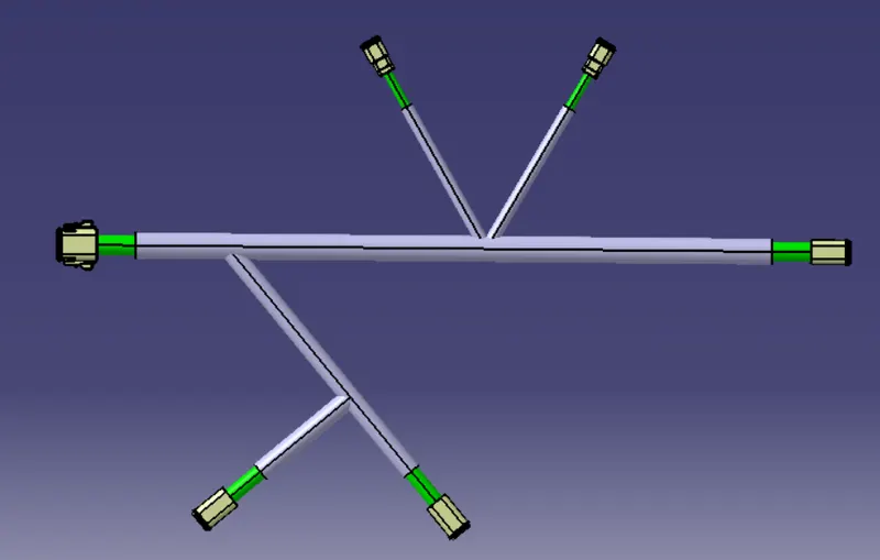
- Bundle flattening has been done from electrical flattening workbench.
- Initial step is to set the Harness flattening parameters using harness flattening parametes option.
- Then next step is to extract Geometrical bundle assembly file from tile vertical window.
- Then next step is flatten the bundle using flatten option, where have to select the plane and choose the bundles for flattening and click ok.
- Then have to arrange the connectors using rotate command.
Creation of Harness Flattening Drawing:
- Harness 2D drawing has been created from Drawing workbench.
- Initial step is to select the front view of the harness flattern assembly, then click ok.
- Then adjust the drawings as per the parameters from properties option.
Conclusion:
Defined the mechanical parts electrically and created the geometrical bundle assembly, then bundle flattening has been done in the CATIA flattening workbench. Then created 2D drawing of the bundle with connector representation and different colour coding for bundle with protective covering and attached the necessary files.