Wiring harness design in CATIA V5 - 3D modeling Week 7 Challenge
AIM : Flatten the harness assembly and place the flattend view on drawing sheet.
OBJECTIVE : The main objective of this project is to bring week4 challenge assembly harness and convert this harness into flat which is done by the use of electrical harness flattening workbench in CATIA V5.
Week4 challenge harness assembly
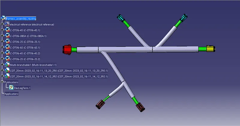
In week4 challenge, there are 6 connector where we have to do routing on that connectors with their given dimension (These dimension parameter add through exteernal reference) and add protective covering on them with 30mm end extrimities. The given figure 1 shown below.
Figure 1: Harness assembly routing in week4 challenge
Now these are the following step to convert harness assembly to flatten file:
- Import the week4 challenge assembly
- Create a new product file
- New product file name "Flattening week4_challeng"
- Switch to the Electrical Harness Flattening workbench
- Add Harness flattening parameters with their specificatioon
- Now we will see the Flattening Parameter added in to model tree
- Once we add flattening parameter in model tree, all the tool appears now in Flattening workbench
- Now import the week4_challenge assembly into the new product file
- For importing the assembly harness, first we click on new product file and then click Extract tool and then click on electrically defined multibranchable in another model tree (week4_challenge)
- Now we will be able to see week4 assembly file imported in new flattenig product file
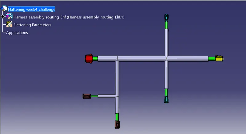
- For Flattening the assembly harness, click on "Flatten" tool command and select the active plane (like normal to the face or xy plane) and then select any bundle and then click on "Select all branch" and then "OK".
- Save the new product file
Figure 2: New product File and adding Flattening parameter


Figure 3: Importing week4 challenge assembly harness into new product file
- 'Harness assembly routing' file convert into 'Harness assembly routing Ehf file'.
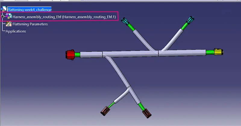
Figure 4: Flattenig the harness routing
- Click on 'Flatten' too command , select active plane, select bundle, click on 'select all brach' and then click 'OK'
These are the following step to place Flattened view on Drawing sheet:
- Create new drawing file
- Click on ribbon File > New > Drawing > Ok
- Select drawing standard - ISO and Sheet style - A0 ISO and click on Landscape and then Ok
- Now drawing sheet will open on screen
- Now importing the flatten view in to the drawing sheet, click on "Front view" tool command And then go to the flatten assembly routing and select connector plane surface as selected previously.
- We will able to see the flatten Ehf file imported into drawing sheet and set as desired position by using of drawing compass
- Update the drawing file
- Right click > properties > view > dress up > 3D wireframe > is always visible
Figure 1: Create drawing file

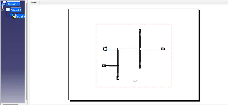
Figure 2: Import Ehf file and convert into 2D
- Import Ehf file - click on "Front view" tool command And then go to the flatten assembly routing and select connector plane surface as selected previously.
- Convert into 2D - Right click > properties > view > dress up > 3D wireframe > is always visible.
- Here we can see that corrogated tube visible, double line with higher diameter and bundle wire visible with only double line and lesser diameter so we can differentiate easily.
CONCLUSION
Here i convert harness assembly into flatten product file and place the flatten view on drawing sheet. Pretective covering are clearly shown in the figure with double line higher diameter and bundle segment only with double line So we can differentiate easily.