Wiring harness design in CATIA V5 - 3D modeling Week 7 Challenge
ANSWER:
- DT06-4S
- DT06-6S
- DT06-2S
- DT06-08SA
We have downloaded the required connectors to perform or create the harness assembly as shown above
We have to define all the mechanical components into the electrical component
Here we have defined them as given below
- Downloading the connector 3D part
- Creating the required geometrical parameters
- Define the part as an electrical connector
- Define bundle connection point
- Define connector connection point
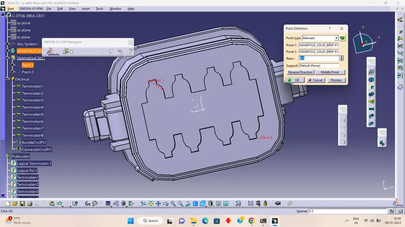
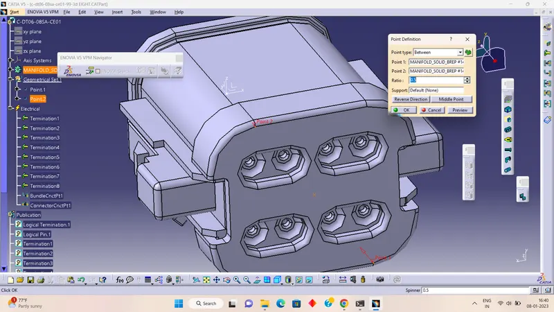
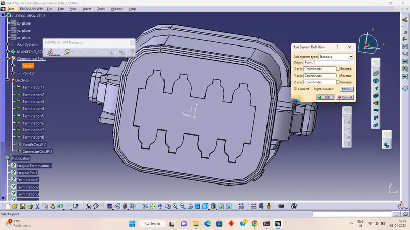
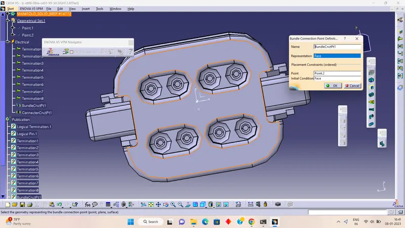
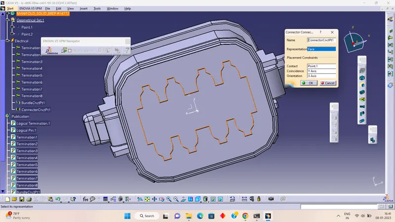
Preparation Of Harness Assembly
As we are done with the wiring harness component design, it is time to prepare the product assembly for the given harness.
Wiring Harness Product Assembly Contains:-
- The Harness Context Assembly:- This is the top-level product file that contains the harness geometrical bundle/assembly and the wire harness electrical bundle.
- Geometrical Bundle:- This sub-level product file is the wire harness product that contains all of the connectors, actual physical bundle segments, and branches.
- Electrical Bundle:- This sub-level product file contains all of the electrical circuit information.
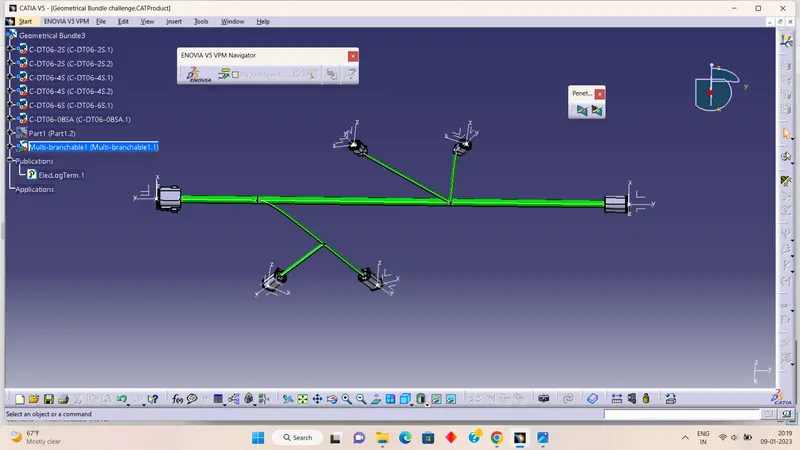
We have to flatten the above harness assembly
HARNESS FLATTENING:
- We then go for the electrical harness workbench and the new product has been created.
- we define the flattening parameters as shown below.
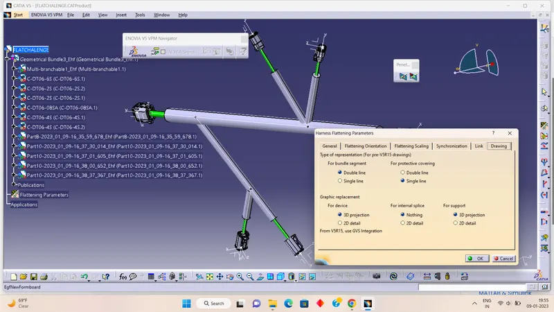
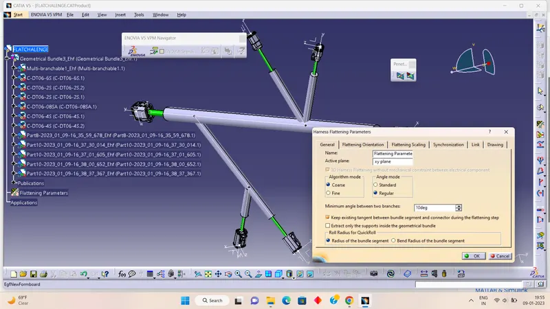
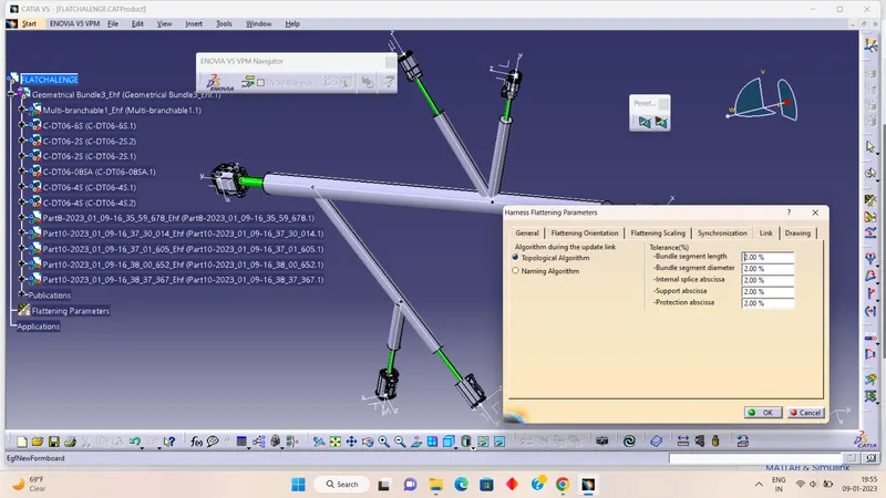
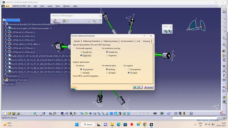
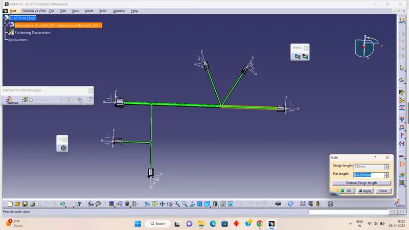
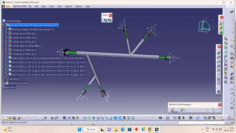
- we extract the harness by using the extract command to flatten the assembly and we provide our required angle, place, and length we use commands like rotate scale quick roll, etc.
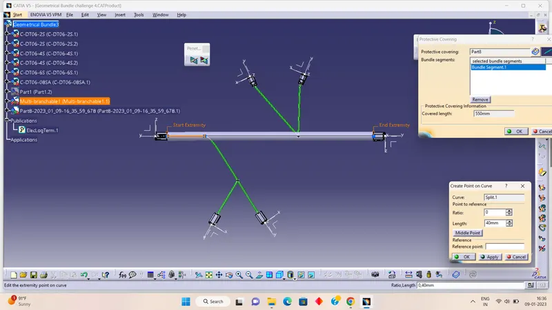
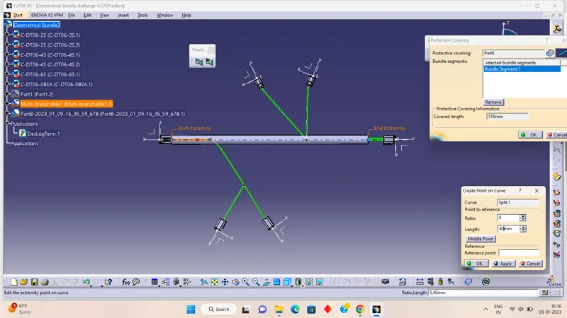
- Then we apply the COT tubes to the harness bundle with the end extremity of 40mm.
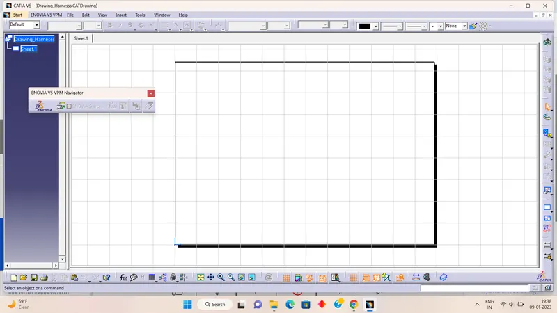
- Then we go for the 2D drawing of the harness by creating the new drawing file we want to create.
- then we select the front face view to draw the harness by selecting the surface of connectors and then we defined the required parameters for the drawing going into the properties.
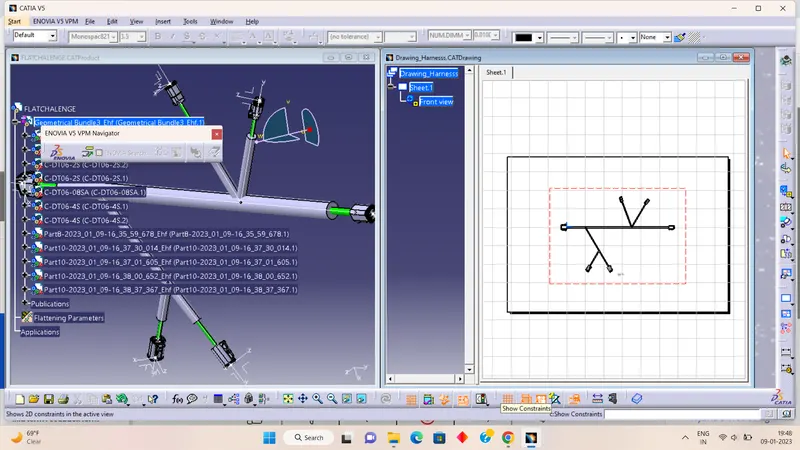
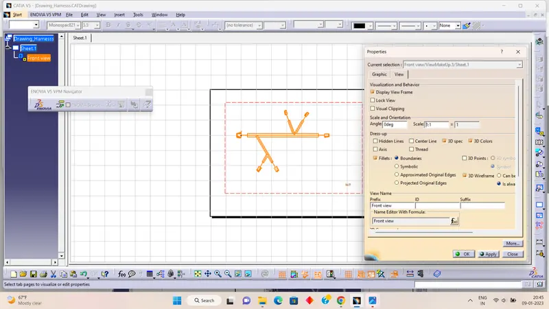
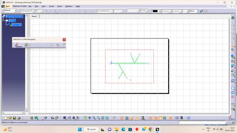
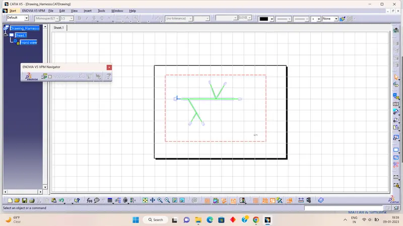
This is how we created the assembly and 2D drawing.