Wiring harness design in CATIA V5 - 3D modeling Week 7 Challenge
| WIRING HARNESS FLATTENING |
AIM:
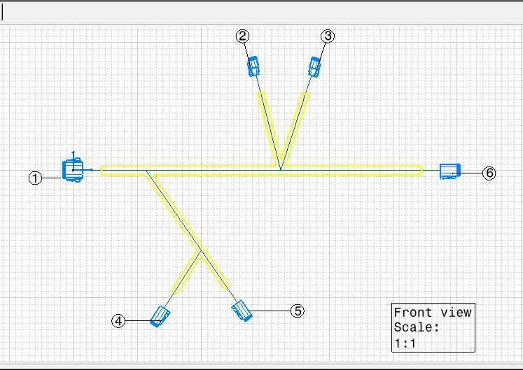
The main objective is to create the Flattened layout for given inputs by using Electrical Harness Flattening and to place it on Drawing sheet.
Inputs:
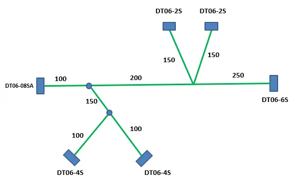
INTRODUCTION:
WIRING HARNESS
A wire harness, often referred to as a cable harness or wiring assembly, is a systematic and integrated arrangement of cables within an insulated material. The purpose of the assembly is to transmit signal or electrical power. Cables are bound together with straps, cable ties, cable lacing, sleeves, electrical tape, conduit, or a combination thereof. The wire harness simplifies the connection to larger components by integrating the wiring into a single unit for “drop-in” installation.
HARNESS FLATTENING
The objective of the flattening process is to create a 2D representation of a wiring harness. The wiring harness flattening consists of assembly of geometrical bundle to form a flatten bundle to get the 2D drawing details. For wiring harness, assembly of geometrical bundle is the main component.
PROCEDURS:
| WIRING HARNESS |
1. Defining the given part as an Electrical Component _
Steps to be followed are,
|
1. Create 3D object/Get from vendor |
| 2. Define Geomentrical parameters |
| 3. Define the 3d object as a connector |
|
4. Define connection points |
Creation of geomentrical parameters such as points and Coordinatinf system,
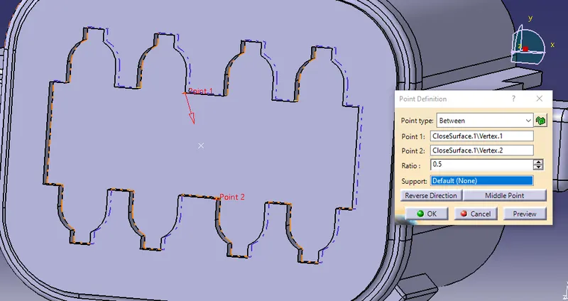
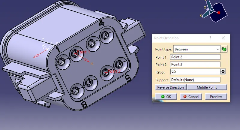
Above image shows pont creating on other side of connector to create bundle connection point.
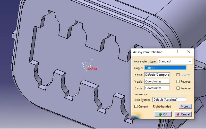
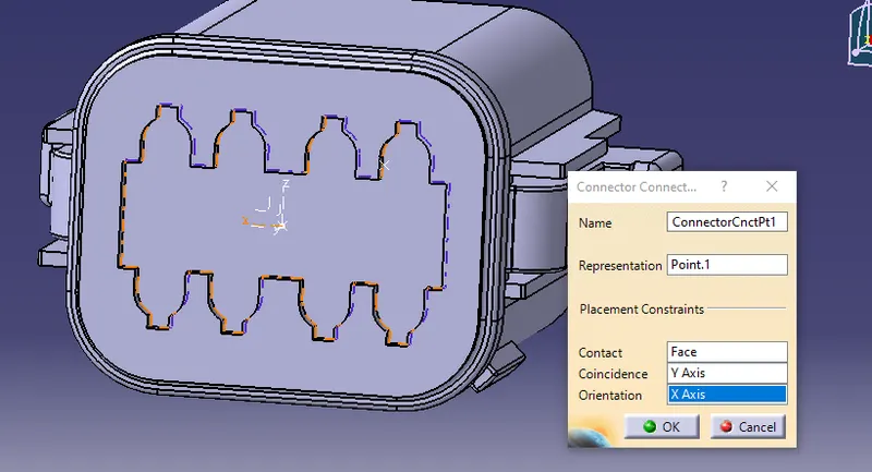
conditions - Y axis should be in the mating direction
x axis should be in the locking mechanism direction
z axis should be in the direction towards top surface
Defining the connector to create connection points,
To create connection points we should have a electrical equipment like connectors, we should define the part or 3d object as an electrical device.
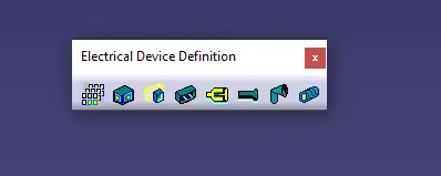 ->Definition toolbar to define the given object as electrical
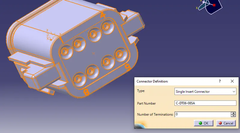
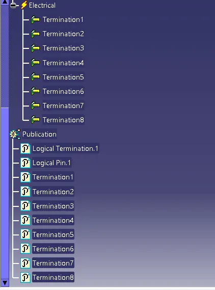
The above image shows The properties of electrical Device.
Electical Connection Point defenition Toolbar
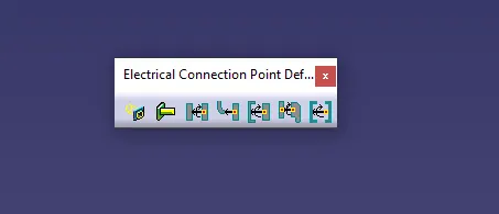 -> this is the toolbar in electrical part design to define connecting points.
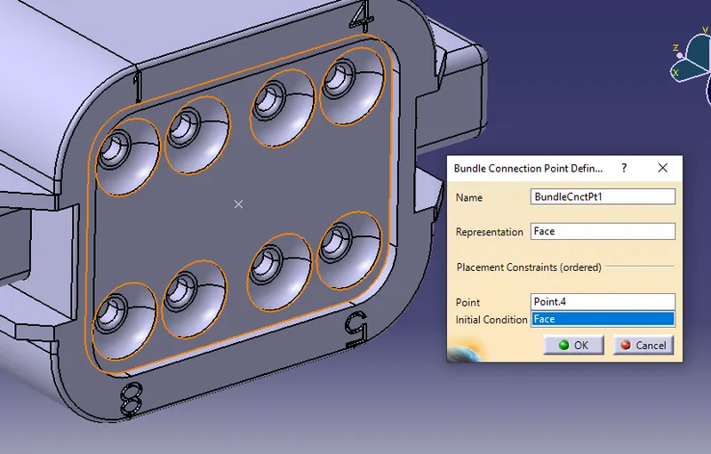
Connector Connection point:
Wiring Harness Assembly Creation
Create the assembly of geometrical bundle product in CATIA V5.
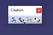 -> Toolbar to Define geomentrical bundle
All the required connectors should be inserted into the geometrical bundle assembly product. Note_All the connectors must be Electrically defined.
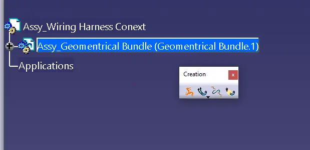
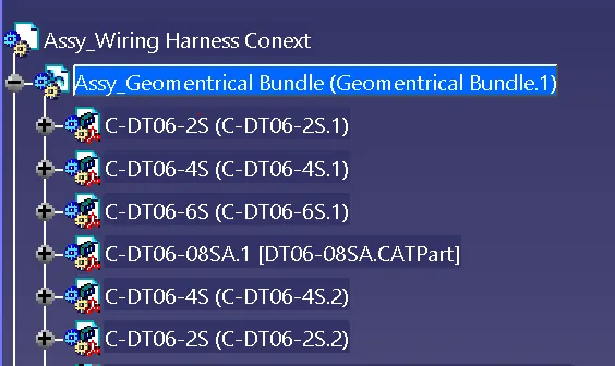
the connectors can be placed at the required positions by using the SNAP, SMART MOVE, COORDINATE SYSTEM and MANIPULATION COMMANDS.
Now enter into the WIRING HARNESS ASSEMBLY workbench.
Multi_Branching:
-> toolbar for multi branching
Bundles are developed between two electrical components by using bundle definition point.
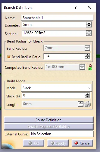
The above image shows creation of bundle.
Bend radius_used to specify flexilibility of bundle. The radius should be minimum of 1.4 times of the bundle Diameter.
Build mode_ used to give extra length The place where the extra lengths are needed. To give the routing from main branch use ADD BRANCH POINT at the required location and give the sub branches.
Now, add the corrugated tubes which are created and saved in COT_TUBES catalogue.
Cover all the branches with corrugated tubes. Give the extremity point from 30 mm.
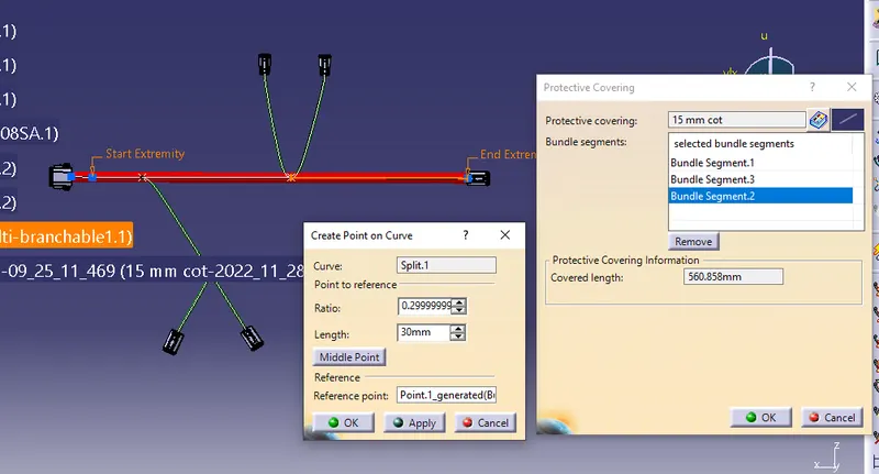
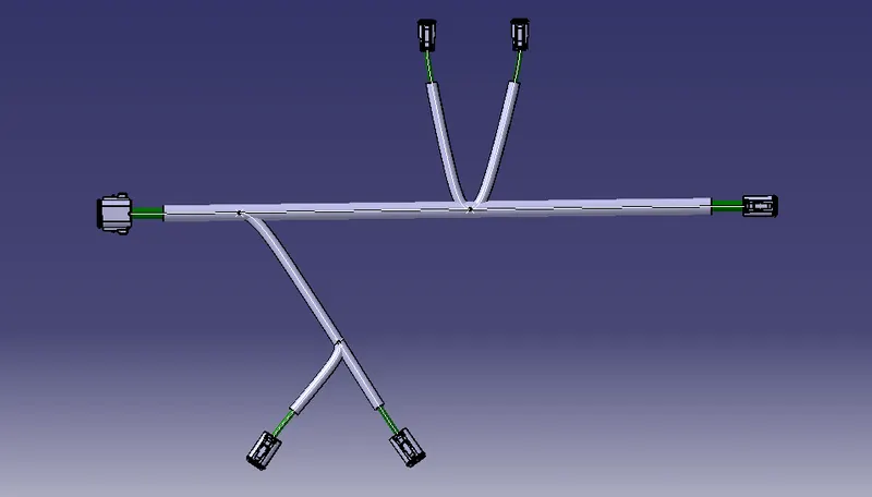
| ELECTRICAL HARNESS FLATTENING |
1) Open a new product file.
2) Go to ELECTRICAL HARNESS FLATTENING workbench. Select the Harness flattening parameters.
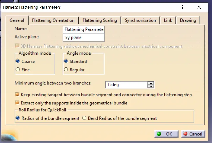
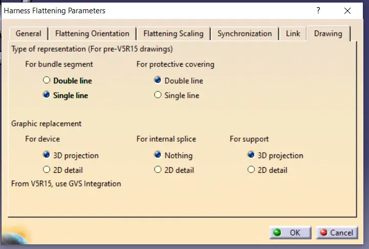
3) Change the parameters accordingly in general and drawing.
4) Make the window tile vertically and place the geometrical bundle in another window.
5) EXTRACT the geometrical bundle into the electrical harness flattening window. Now the geometrical bundle name is changed into the geometrical bundle Ehf (Electrical harness flattening).

6) Now select the FLATTEN command and select the bundle, the entire geometrical bundle will be flattened.
 -> Toolbar which is used for Harness flattening.
7) There are commands like ROTATE, ROLL, QUICK ROLE, SYNCHRONISE which helps to modify the flatten bundle according to our requirements.
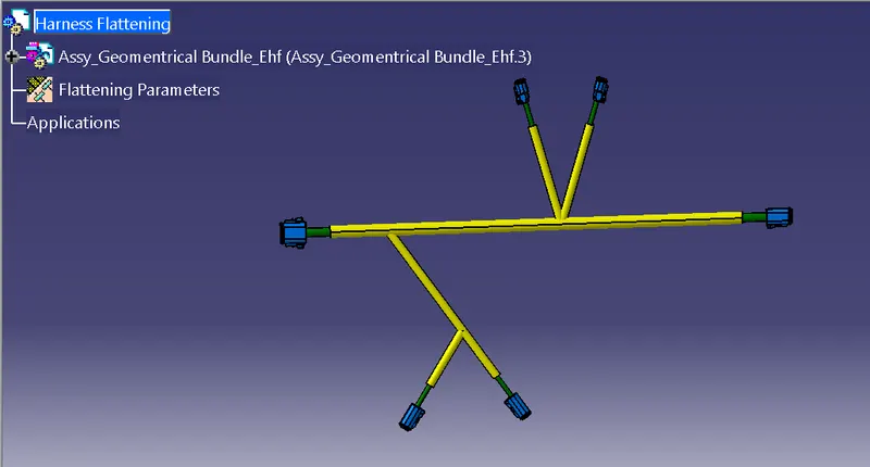
8) Consequently, synchronize option is used to update layout if any changes were made in geomentrical bundle.
| 2D DRAWING |
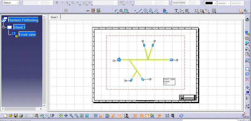
It's developed to represent the 3D objects in 2D drawing. It will be standardized to share among all the stakeolders.
it consist of,
| Layout and Dimensions |
| Connestion table |
| Bill of Material |
| component orientaion and assembly instruction |
After defining orientaion the required properties can be changed to meet desired results.
| RESULT |
CONCLUSION,
- Thus the required Flattened layout has created for wiring harness by using Electrical harness flattening
- 2D Drawing for Flattened layout has created succesfully.