Wiring harness design in CATIA V5 - 3D modeling Week 5 & 6 Challenge
AIM
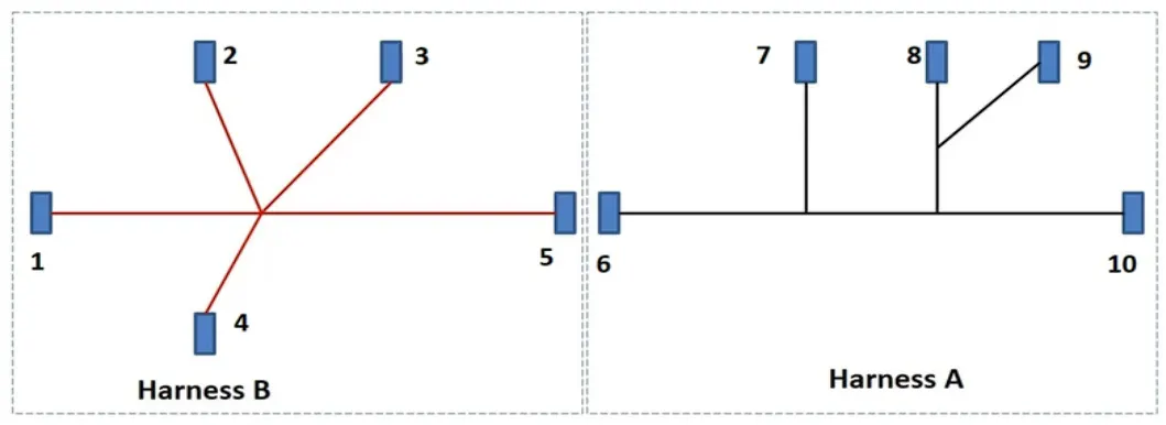
To Route the specified harness configuration on the electrical workbench. Then, verify bundle continuity, annotate every connector, look for bundle warnings, generate the CAT part of the harness assembly, and convert it to the .igs format.
GIVEN LAYOUT
PROCEDURE
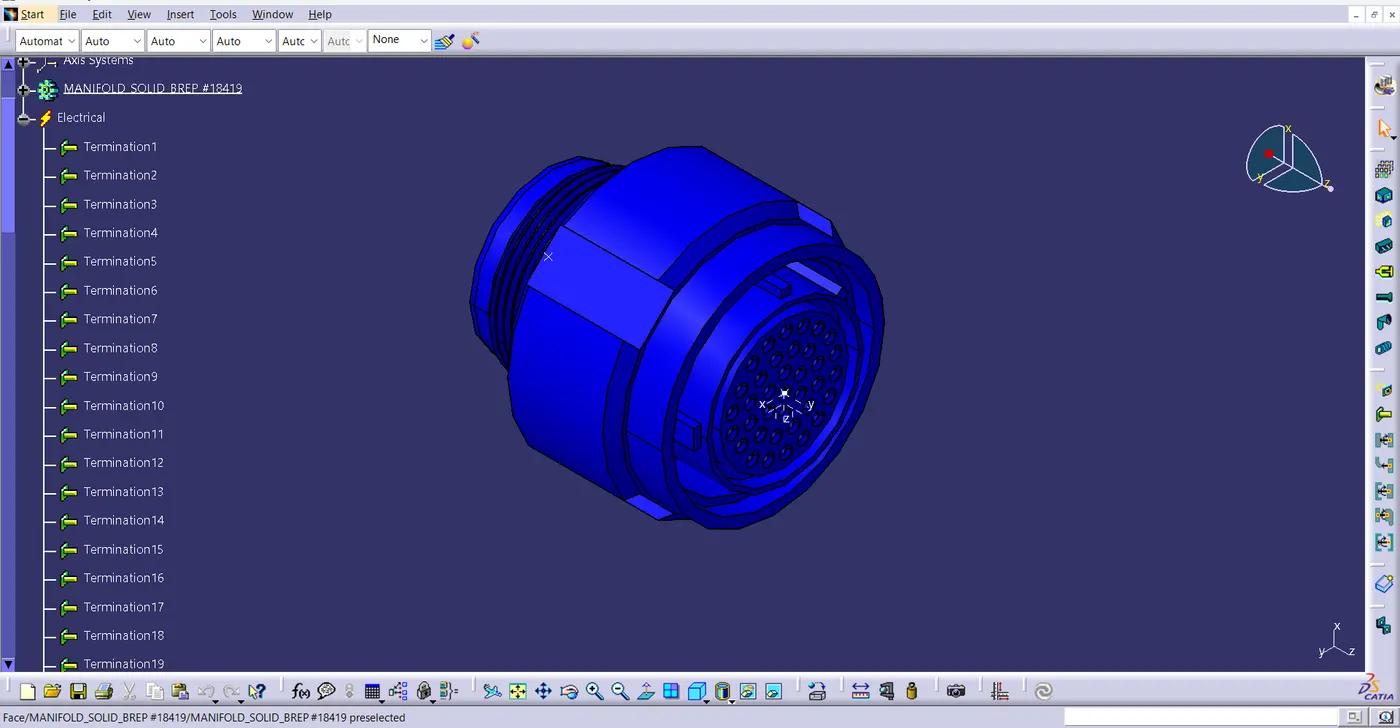
- Acquire the CAD files for the required connectors.
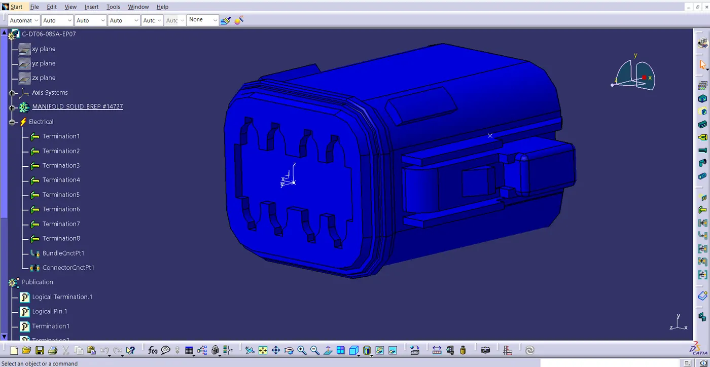
- Convert the acquired mechanical parts into electrical parts by the following steps,
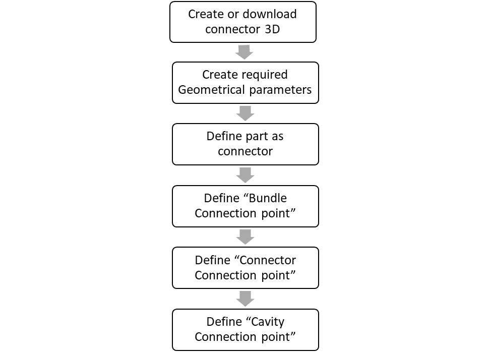
- Bring all of the converted connectors into the electrical harness assembly workbench after they have been converted into electrical parts.
- Then, use the move, snap, translate, or rotation commands to arrange each connector in the desired location. Route it by giving route definition.
Parts and Assembly of Harness B
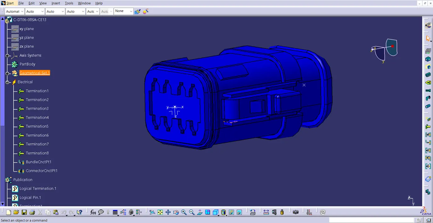
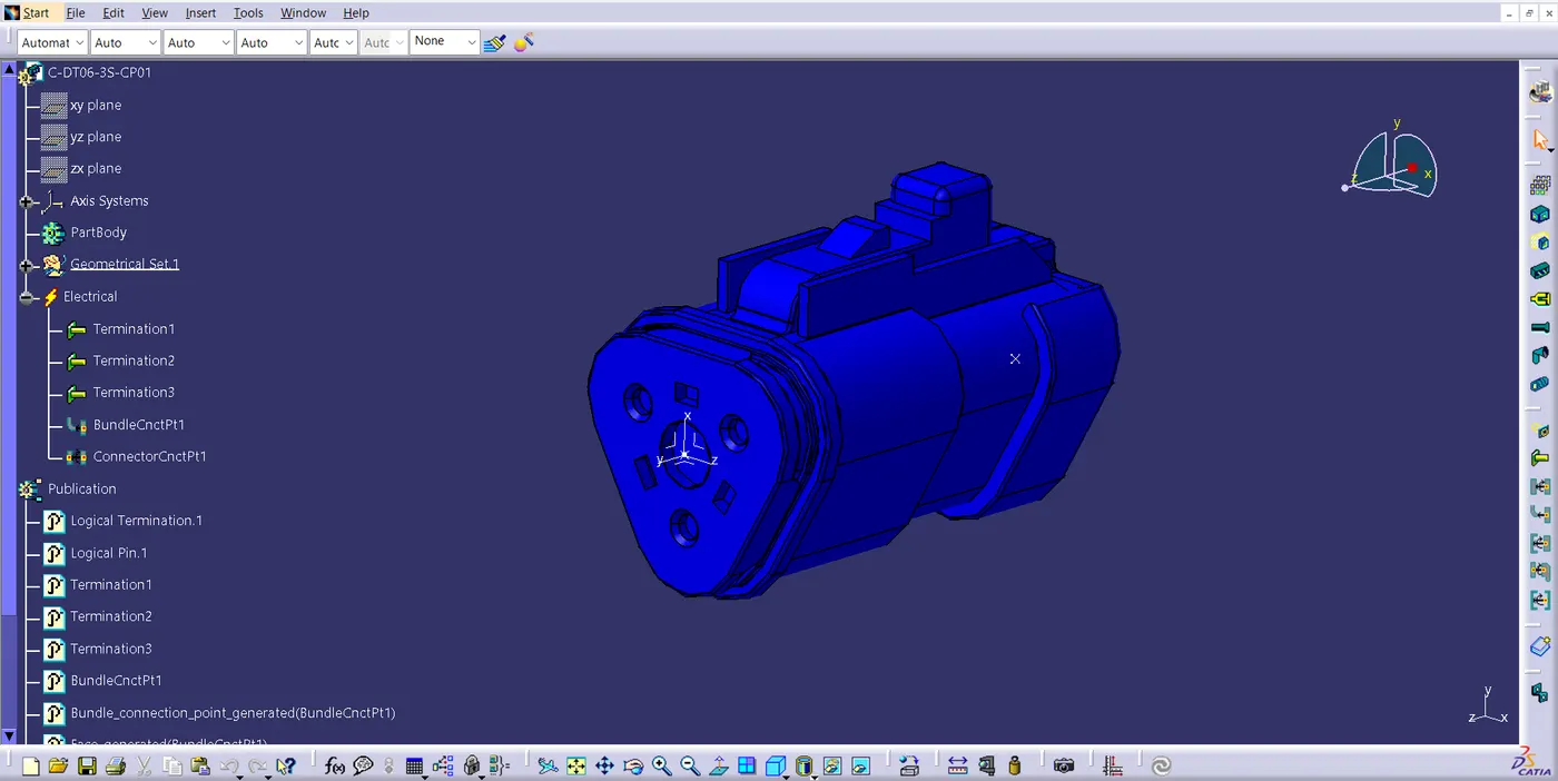
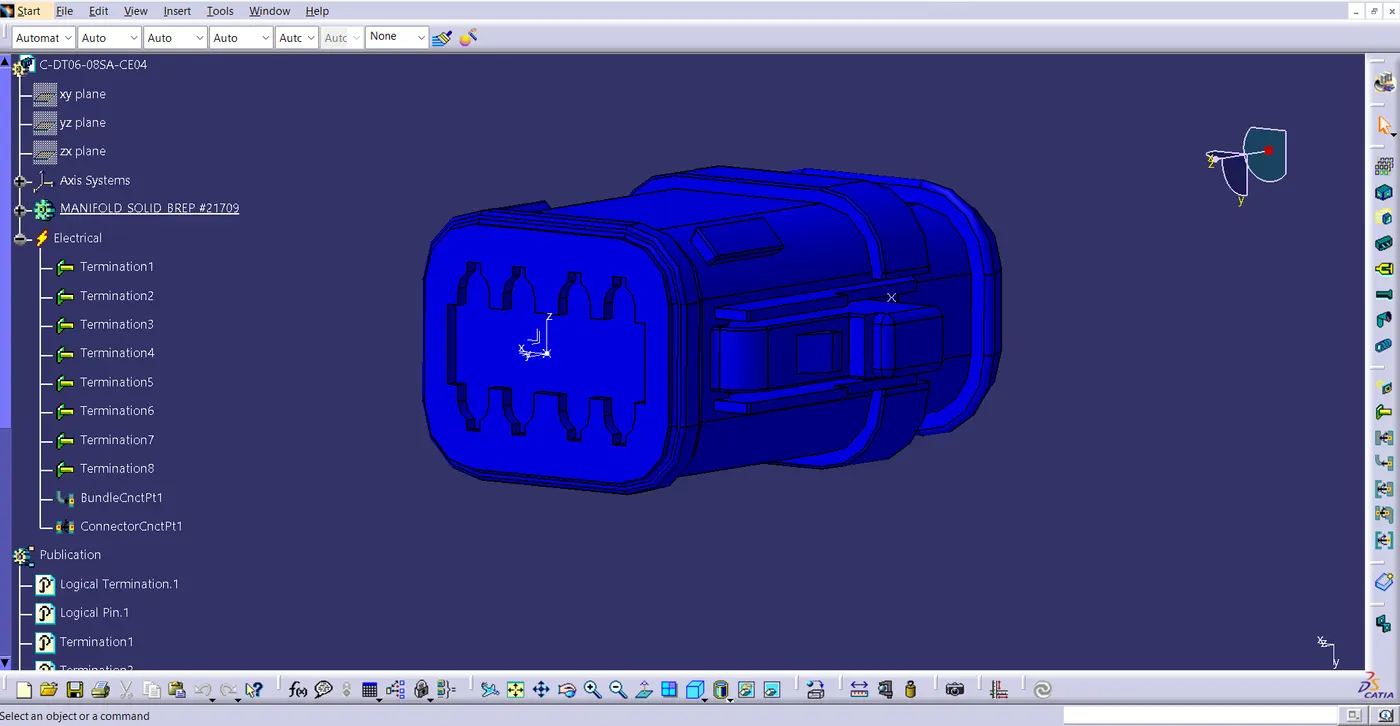
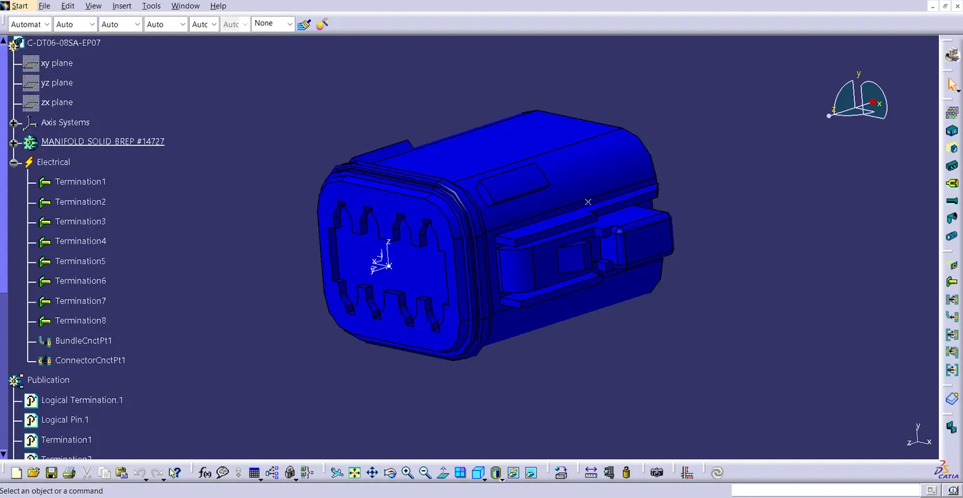
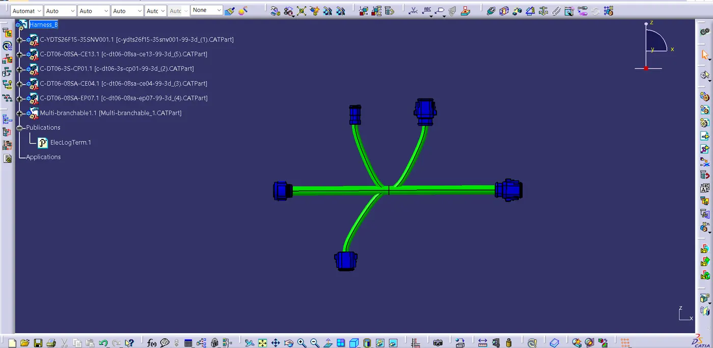
Parts and Assembly of Harness A
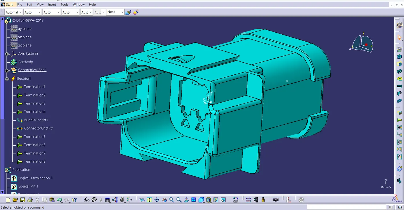
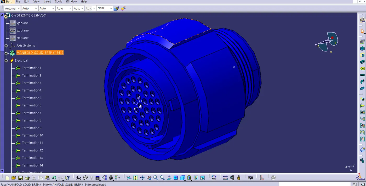
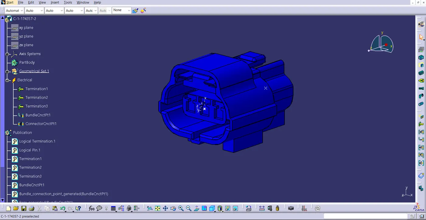
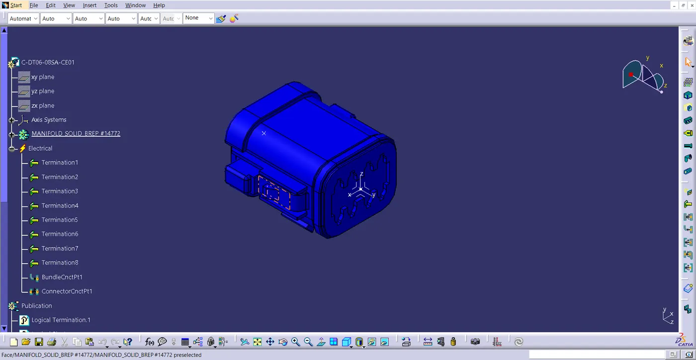
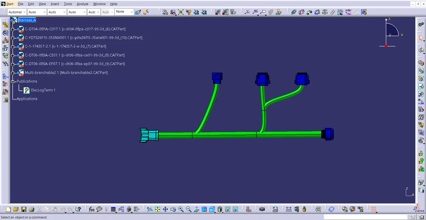
ASSEMBLY OF HARNESS A AND B
- After creating the Harness A and Harness B separately, Bring those two files to the Electrical assembly design as a single product file.
- Then, Using the Connect electrical device command, connect the required electrical device. Here connector 5 and connector 6 is connected.
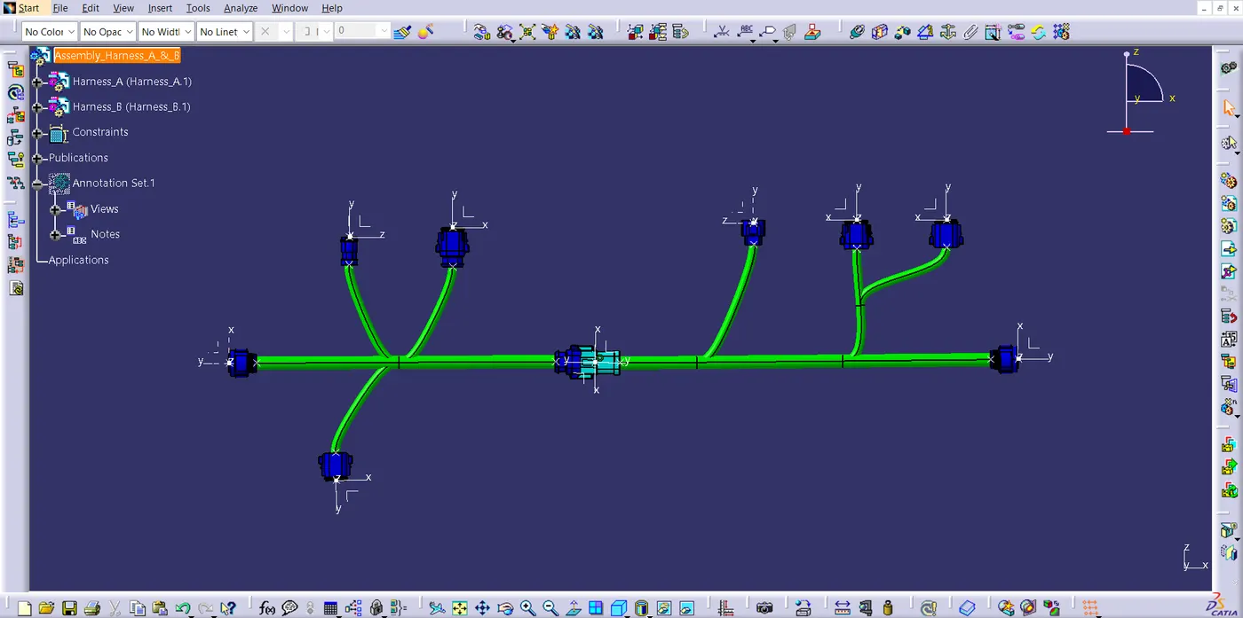
ANNOTATION
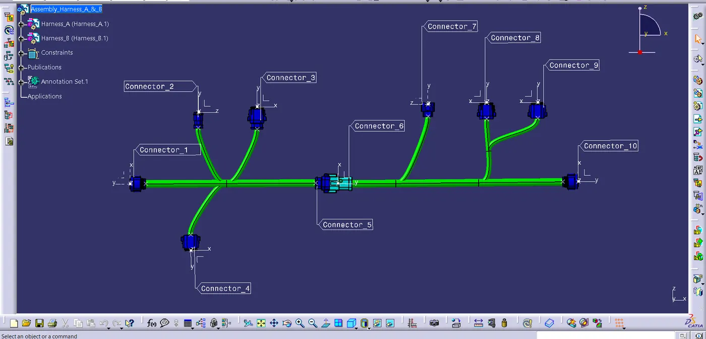
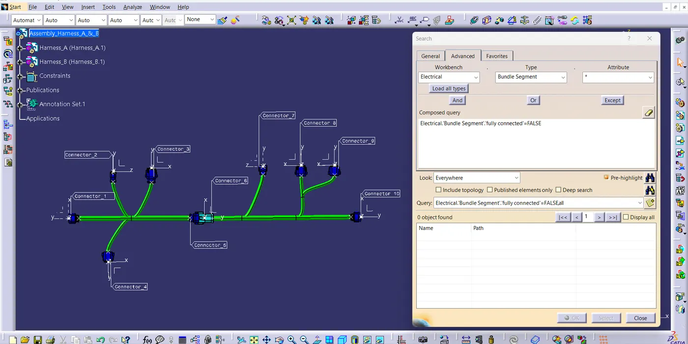
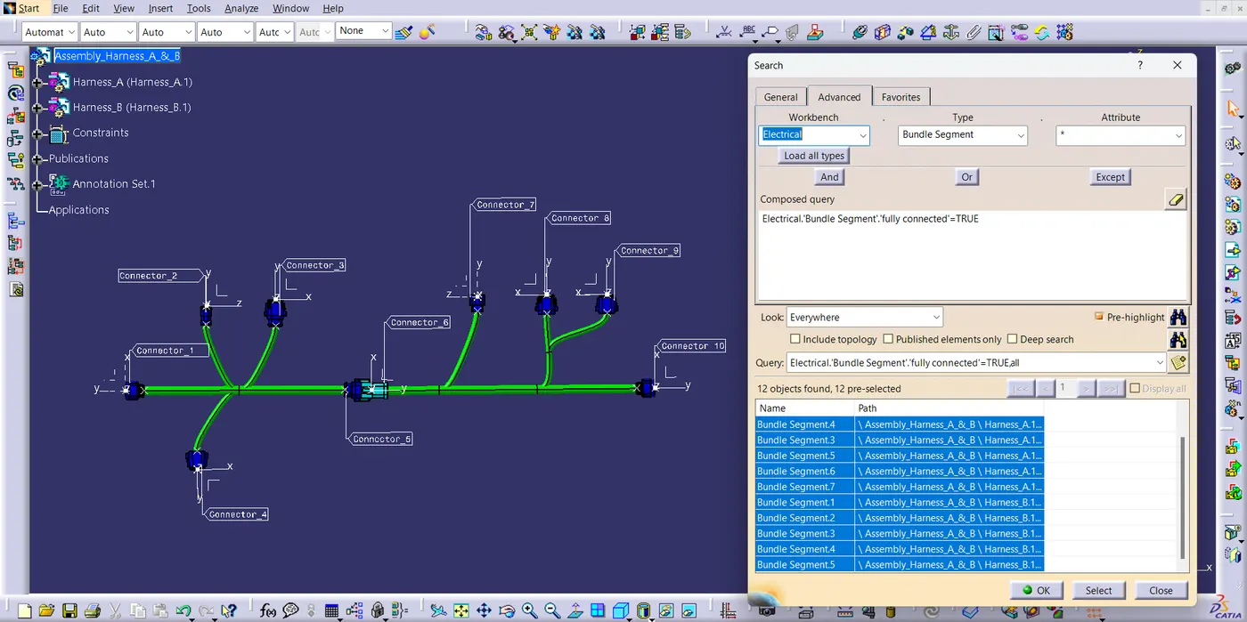
CONNECTIVITY CHECK
- Using search command in Edit toolbar, check the connectivity
- I have given the snaps of both the False and True attribute criterion respectively.
PART BODY CONVERSION
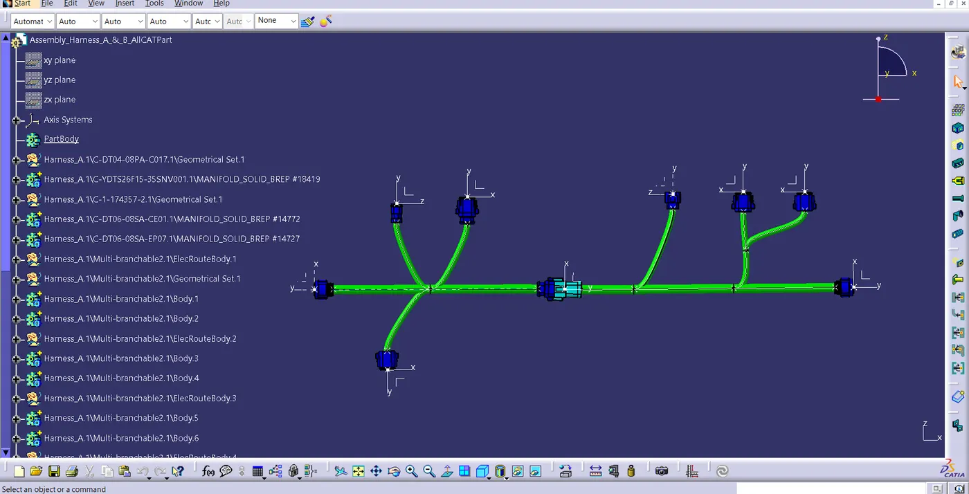
- The electrical assembly product is converted into the Part body with the help of "Generate CATPart from product" command in the Tools toolbar
RESULT
Using CATIA V5 the required harness is created. Checked the connectivity, annotated every connector and the electrical assembly file is converted into the part body file. Also, the converted it into the .igs file.