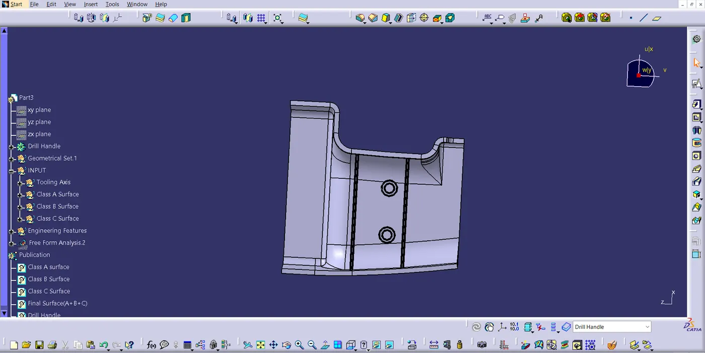
Week 10 - Challenge 1- Attachment Feature Creation (Ribs & Screw Boss)
Week 10 - Challenge 1- Attachment Feature Creation (Ribs & Screw Boss)
AIM:
-
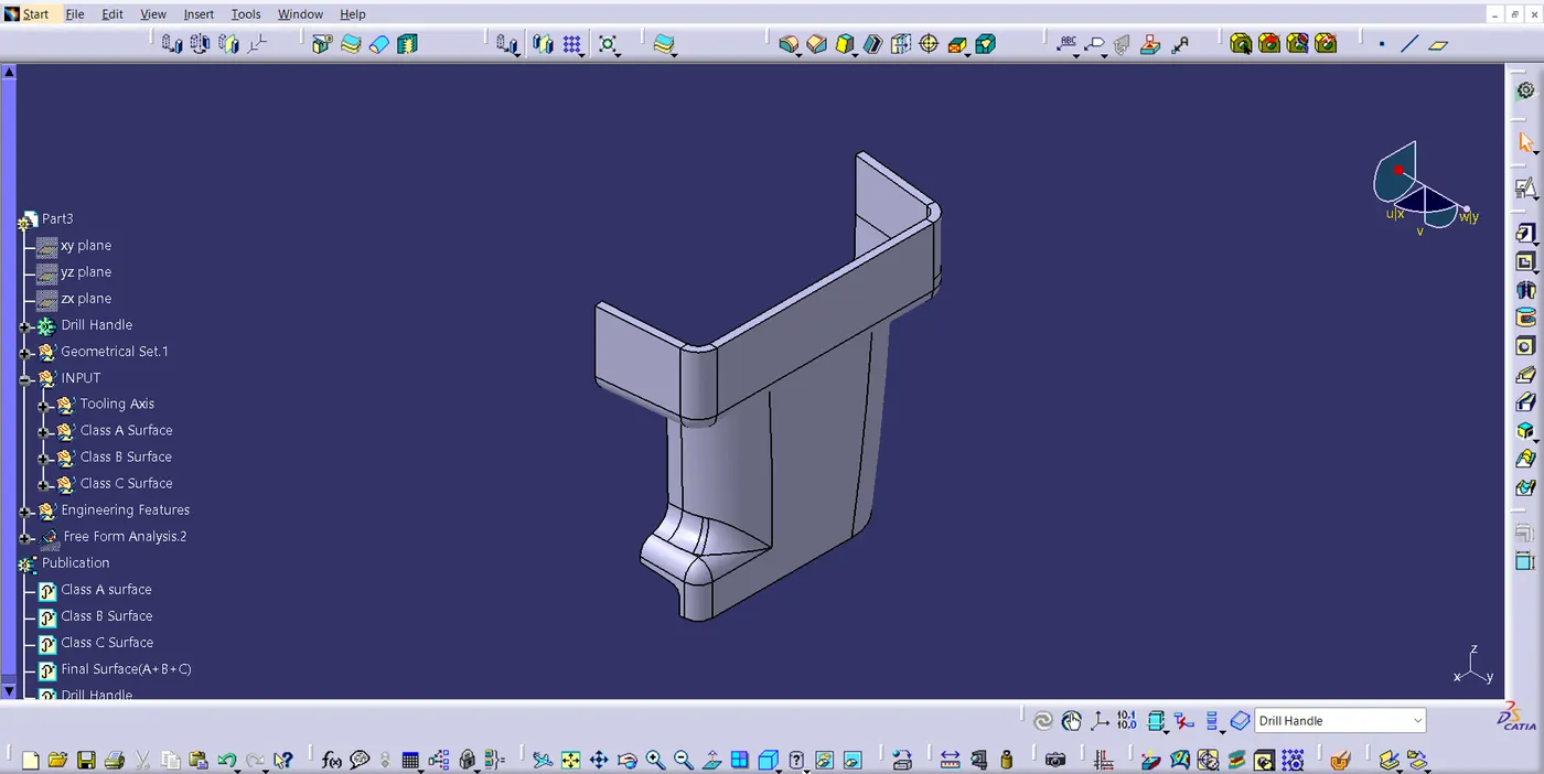
To use the supplied Class-A surface to create the Door Handle Component.
-
To create the tooling axis that satisfies the draft angle requirements for the specified Class-A Surface.
-
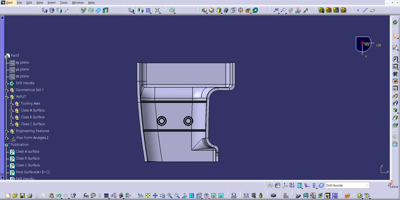
To attach the component's B side features.
-
To run the model through the Draft analysis.
Class A Surface:
To begin with this, a tooling axis is created for the Class A Surface, meeting the requirement of draft angle. he Tooling Direction is basically the direction that the mold pulls a part. The mold is built in two separate pieces, basically. You have a Cavity side and you have the Core side. The Core pulls apart from the Cavity and that's the Dye line or the Tooling Direction. After that, I created the offset of Class A Surface in the inner direction to the thickness of 2.5mm.
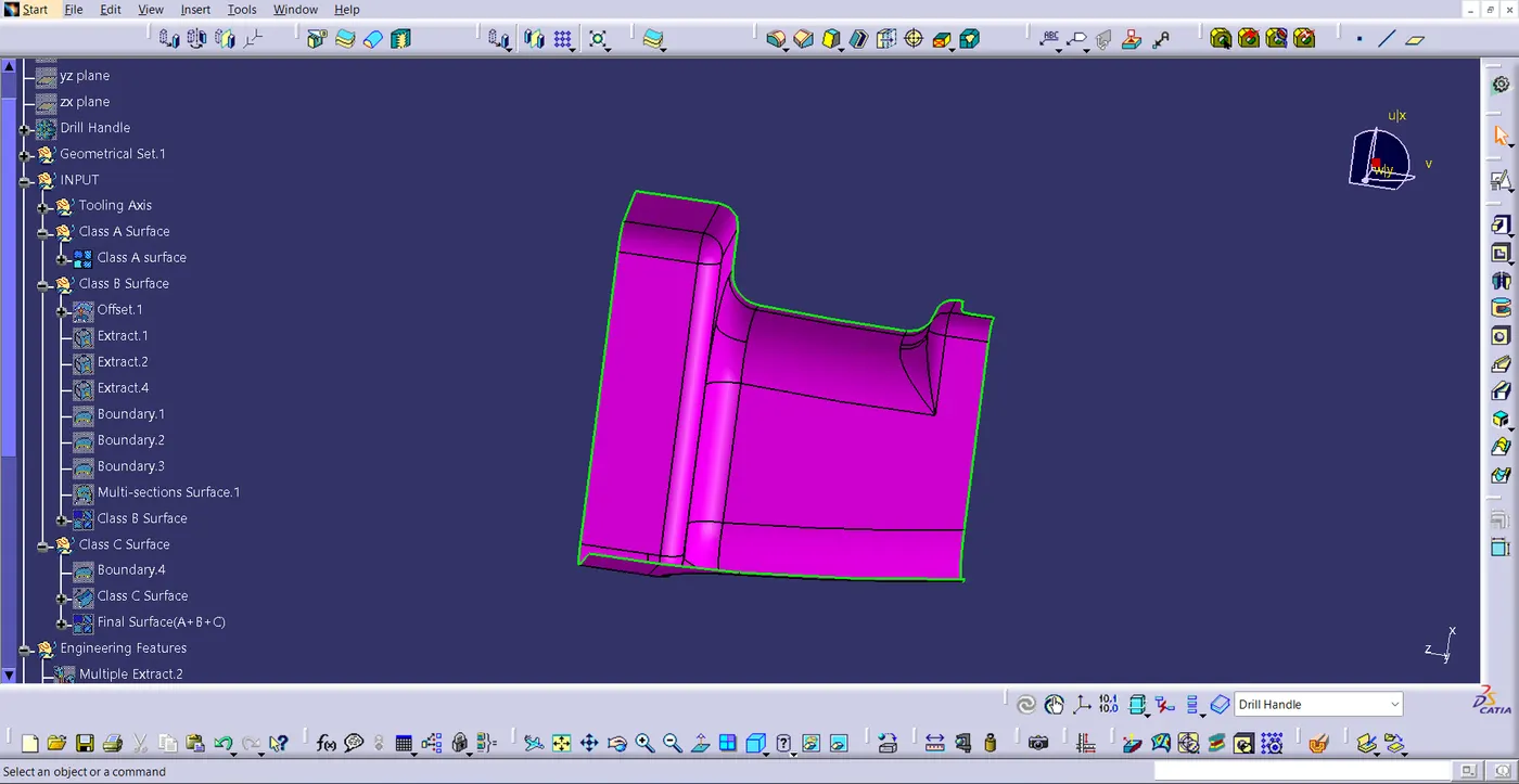
Class B Surface:
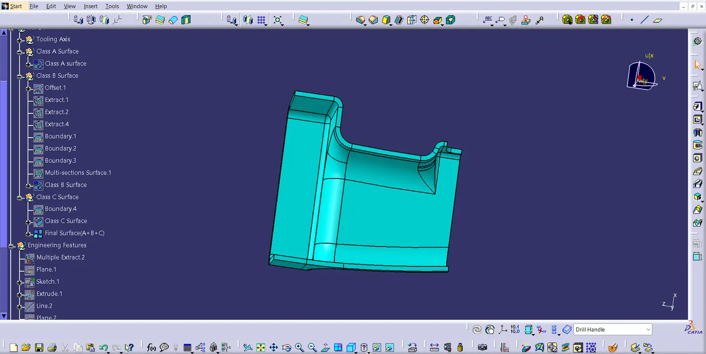
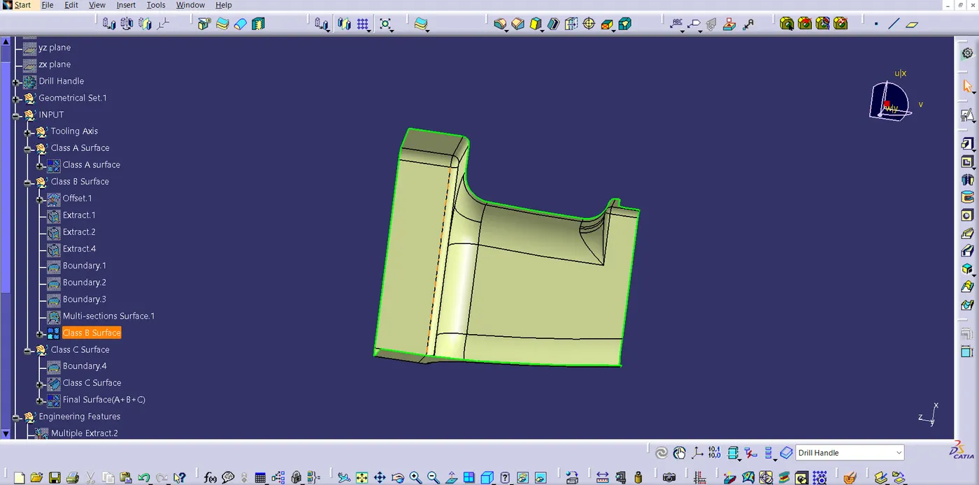
I created the offset of Class A Surface in the inner direction to the thickness of 2.5mm. Next, I saw some patches in the created offset. The main reason for the patches is fillet on the Class A Surface. Once the patches are cleared, I joined them to create Class B Surface
Class C Surface:
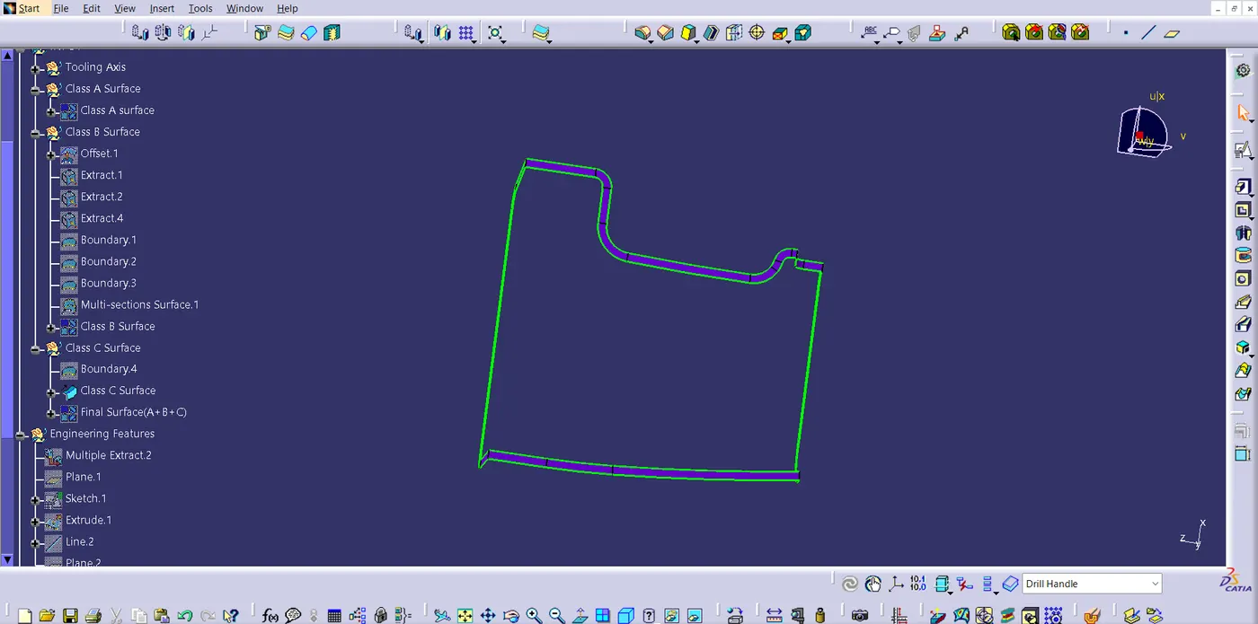
Sweep the boundary of the Class A surface, so that, i can create Class C surface. After Class C Surface is made, Join all the three classes to create a closed part.
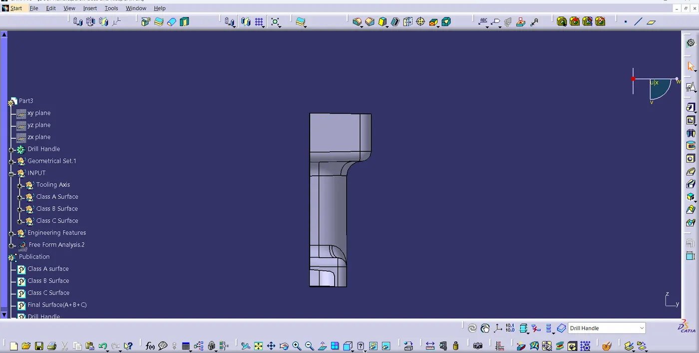
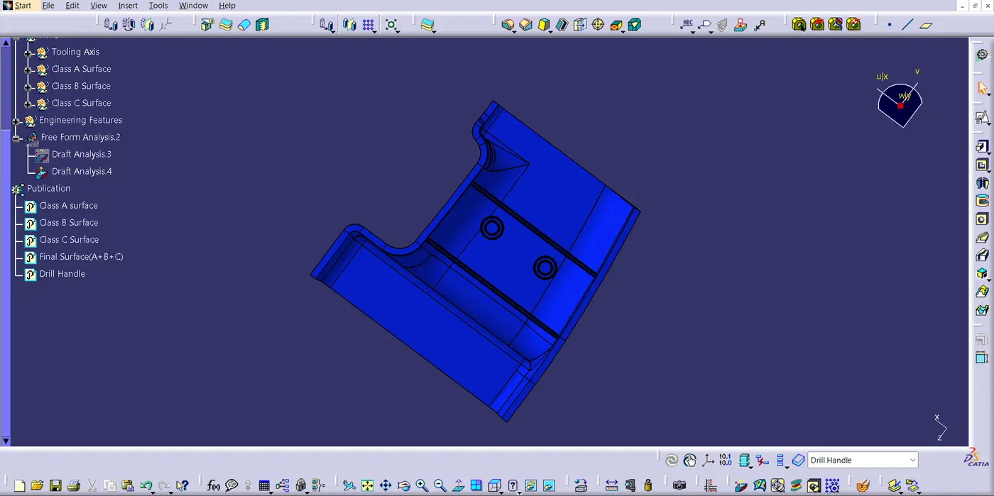
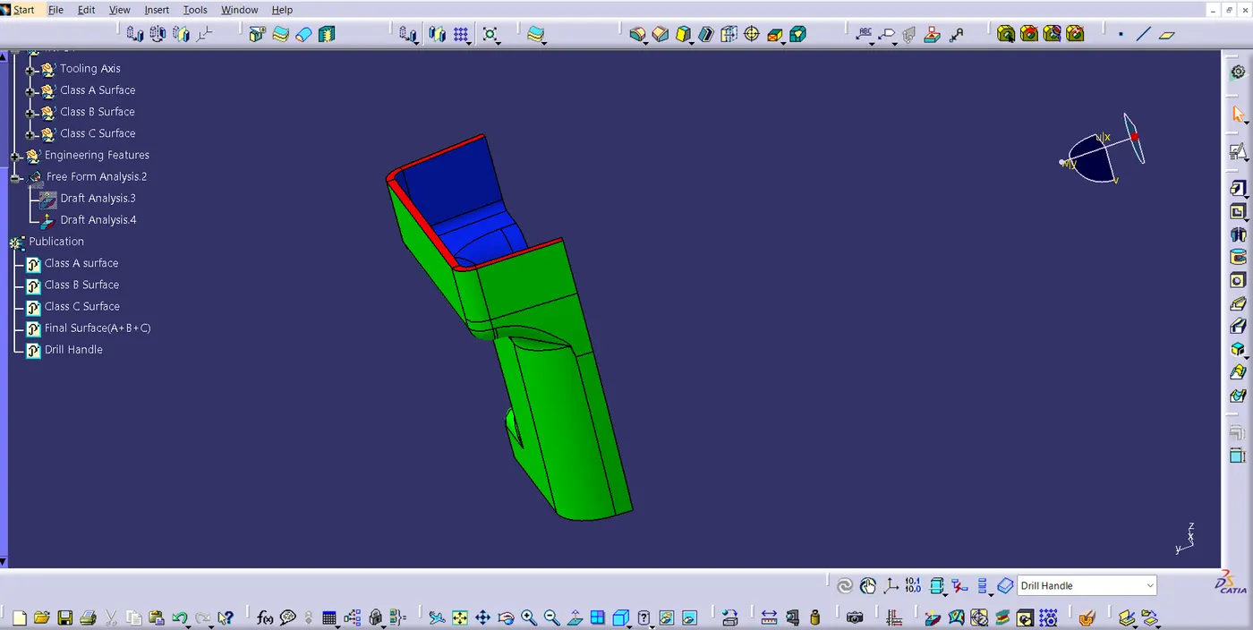
Then, In Part design workbench, closed surface command is used to create solid part. Now, after creating this, Locator and Heat Stakes are made. Finally, I performed draft analysis to check whether all the surface are drafted properly or not.