Wiring harness design in CATIA V5 - 3D modeling Week 5 & 6 Challenge
AIM-:
- DEFINE THE MECHANICAL COMPONENTS ELECTRICALLY AND PREPARE THE CATALOGUE FOR THE SAME.
- CHECK THE BUNDLE IS CONTINOUS AND THE ANNOTATIONSA RE ADDED FOR ALL THE COMPONENTS IN THE ASSEMBLY.
- PREPARE THE INTERCONNECTION FOR HARNESS A AND B.
- CHECK FOR ANY BUNDLE WARNINGS AND SUGGEST WHAT CHANGES ARE MADE. ALSO CREATE .Catpart FROM THE ASSEMBLY BY USING CONVERT CATPRODUCT TO CATPART OPTION.
1. DEFINE THE MECHANICAL COMPONENT ELECTRICALLY
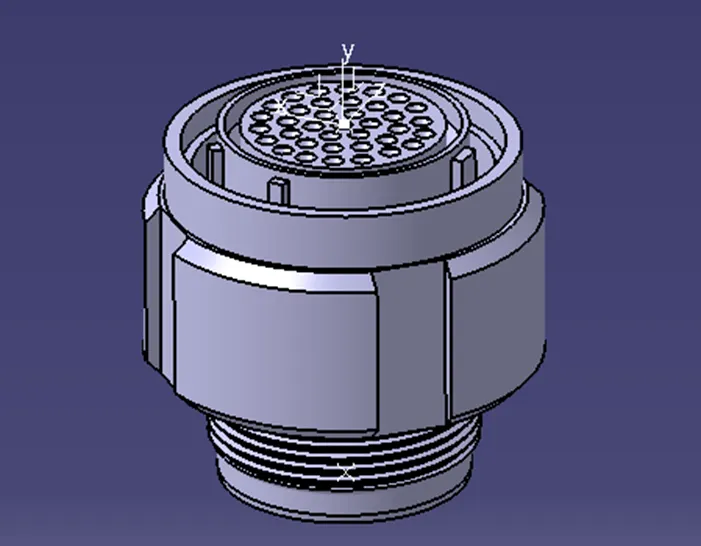
A) CREATE REQUIRED GEOMETRICAL PARAMETERS
- Open the download file in Catia.
- Go to the "Part Design" Work bench by clicking on "Start" then "Part Design".
- Create two point in middle portion for connector connection point and bundle connection point.
- Create the axis on Connector connection point.
- Go to the “Electrical Part Workbench”.
- The “Y axis” should be in the direction of mating face by right click on X axis and rotate by giving angle value.
-
“X axis” on the horizontal direction and “Z axis” in the Top direction by right click on Y axis and rotate by giving angle value.
B) DEFINE PART AS CONNECTOR
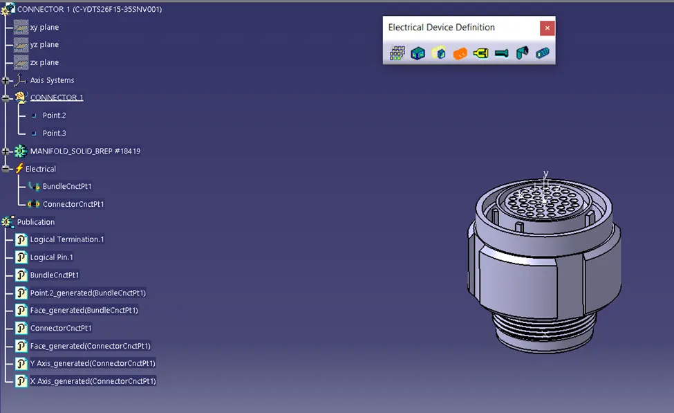
- Go to the “Start” then choose “Equipment & Systems” then choose “Electrical Harness Discipline” then choose “Electrical Part Design”.
- Go to the “Electrical Part Design” workbench.
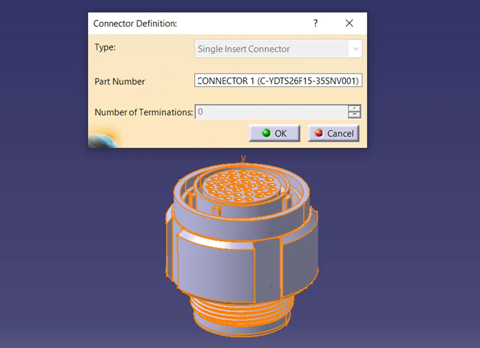
- Click on the body for Connector Definition box.
C) CREATE TERMINATION POINT
- In “Type” option choose “Single Insert Connector”
- For “Part Number” save name as it is.
- For “Number of Terminations”, Count the number of hole and put the value.
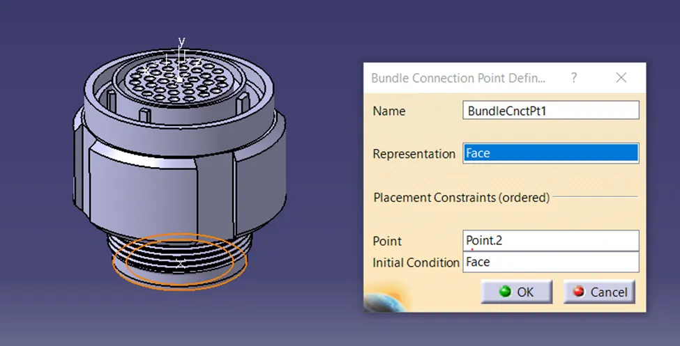
D) DEFINE BUNDLE CONNECTION POINT
- Go to the “Electrical Connection Point Definition”.
- Choose “Define Bundle Connection Point”.
- Select the Connector body for Bundle connection point definition box.
- “Name” left it as it is or right the name here.
- Choose “Representation” option and choose the mating face of connector.
- Choose “Point” option and select the point from connector.
- Choose “Initial Condition” and select the mating face of connector again.
- Then click on ok.
E) DEFINE CONNECTOR CONNECTION POINT
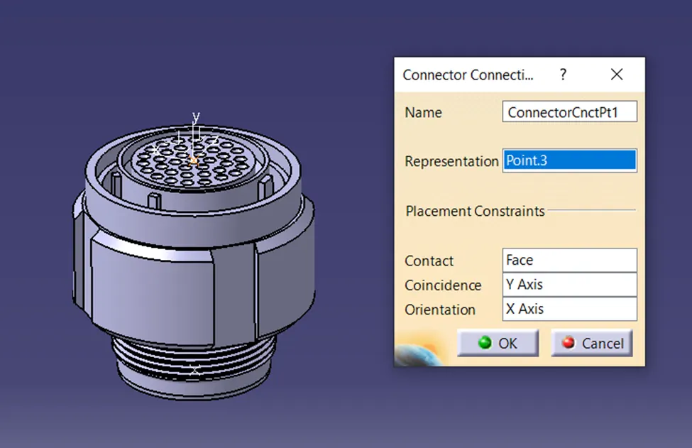
- Go to the “Electrical Connection Point Definition”.
- Choose “Define Connector Connection Point”.
- Select the connector body for Connector Connection Definition box displayed.
- For “name” left it as it is.
- Choose “Representation” option then select the entry point of connector.
- Choose “Contact” option then click on the mating face of the connector.
- Choose “Coincidence” option and select the “Y axis”.
- Choose “Orientation” option and select the “X axis”.
- Click on ok.
FOLLOW THE SAME METHOD AND DEFINE ALL PART ELECTRICALLY
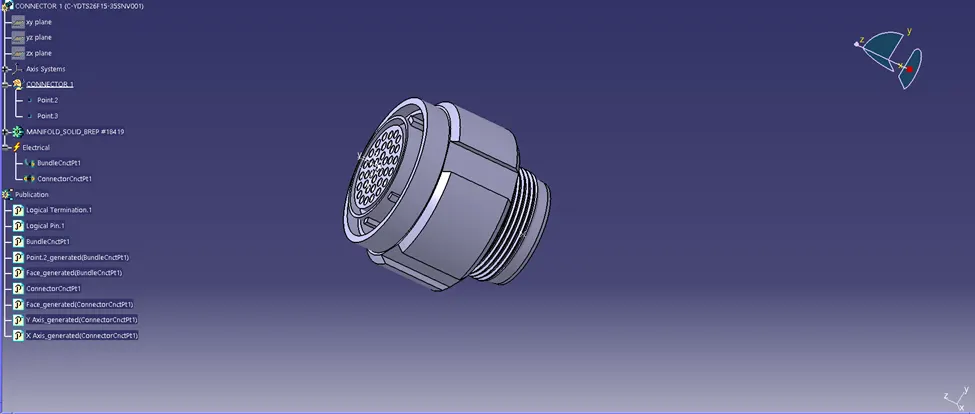
a) CONNECTOR 1
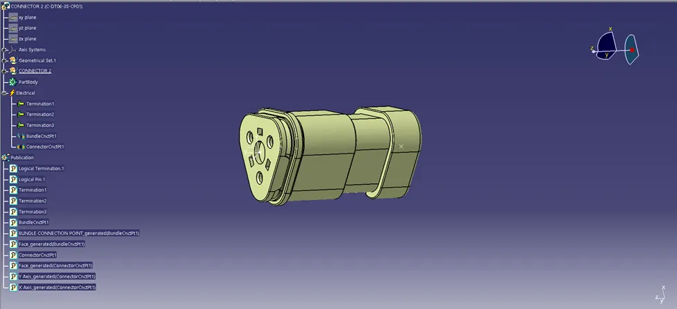
b) CONNECTOR 2
c) CONNECTOR 3
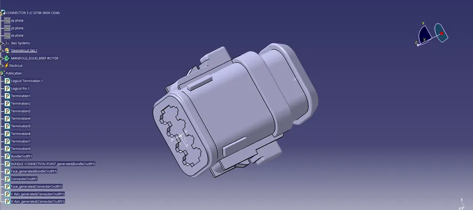
d) CONNECTOR 4
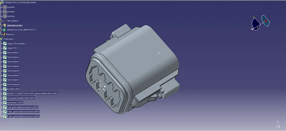
e) CONNECTOR 5
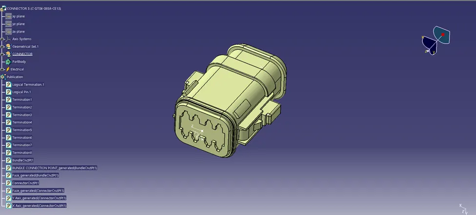
f) CONNECTOR 6
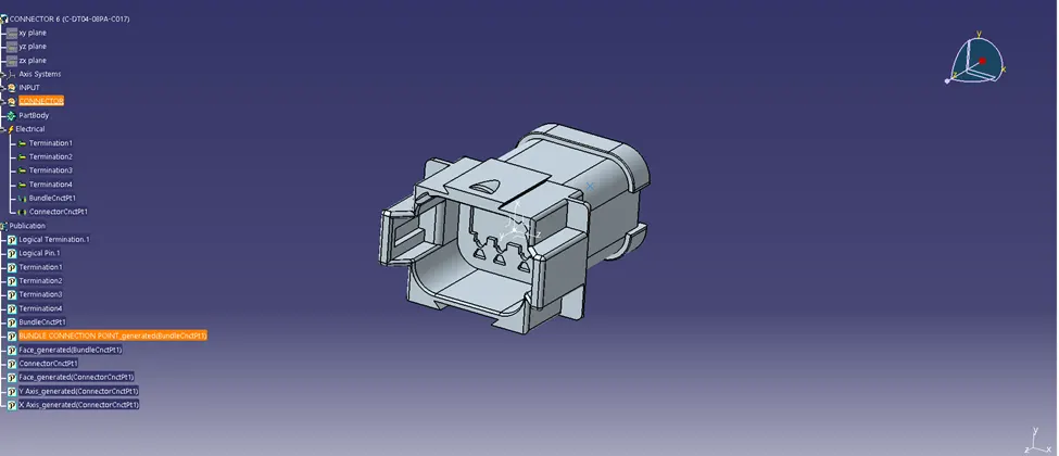
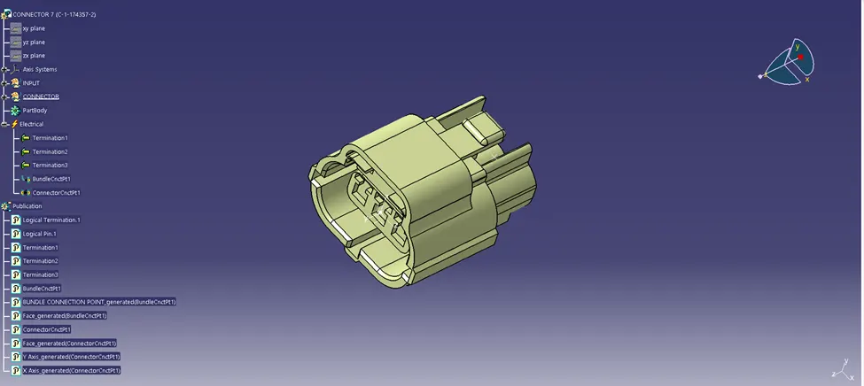
g) CONNECTOR 7
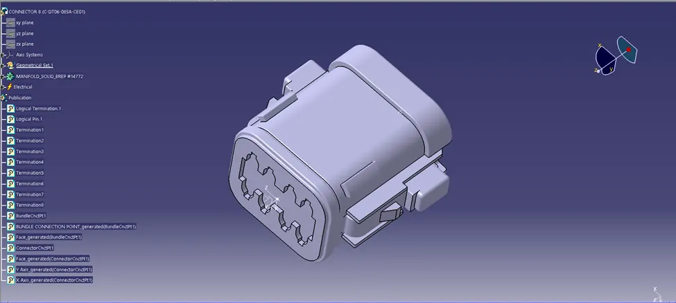
h) CONNECTOR 8
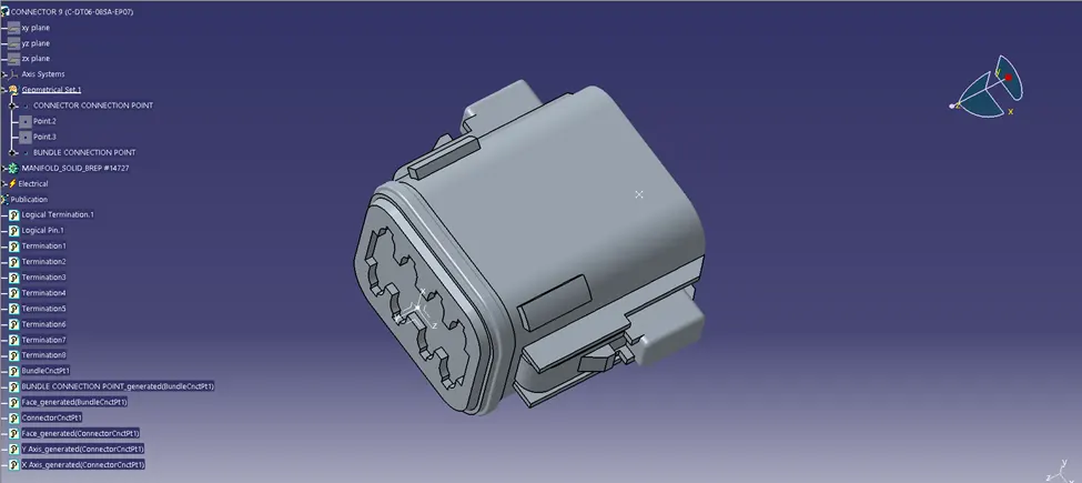
i) CONNECTOR 9
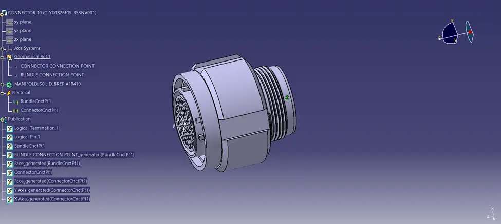
j) CONNECTOR 10
2. CREATE CATALOG FOR ALL CONNECTOR
A) OPEN CATALOG DOCUMENT WORKBENCH.
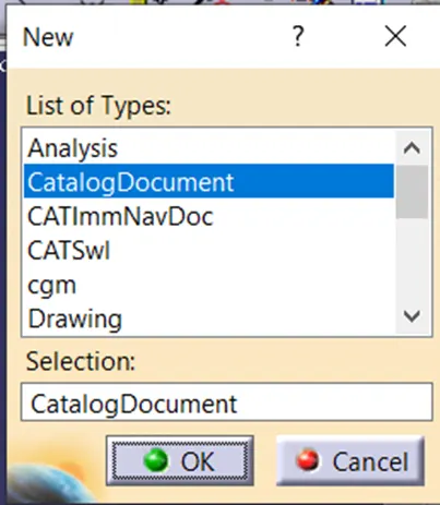
- Go to the “file” option, choose “new”.
- Then select “CatalogDocument” option to open the Catalog Workbench.
B) CREATE CONNECTOR CATALOG
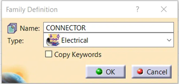
- Select “Add Family” option.
- In “family Definition, Name it as “connector”.
- On “Type” choose “Electrical”.
- Then click on ok.
- Then save this file as “Connector Catalog Doment”.
C) ADD CONNECTOR IN CATALOG DOCUMENT
- Open connector file.
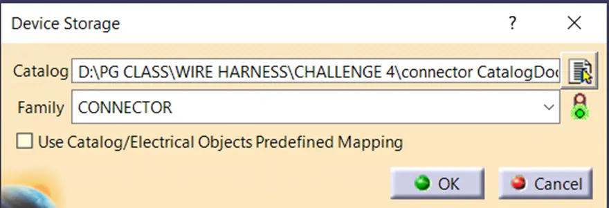
- Choose “Store Device” option.
- Add path in “Catalog”
- Select “Family” as connector, then click on ok.
- Do it for all connector.
3. CREATE SKETCH OF HARNESS A AND HARNESS B
- Open part workbench file.
- Select “sketch” command, then select a plane.
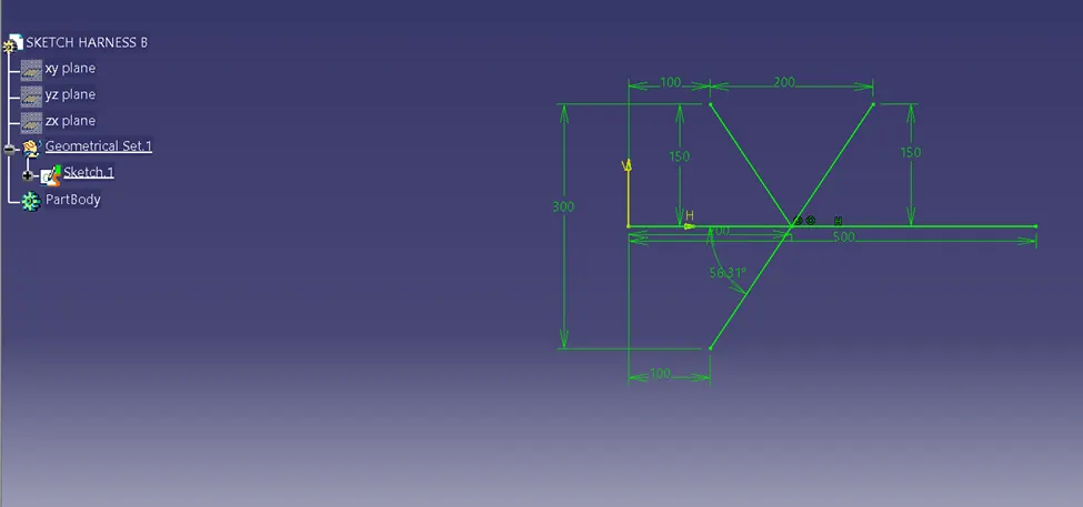
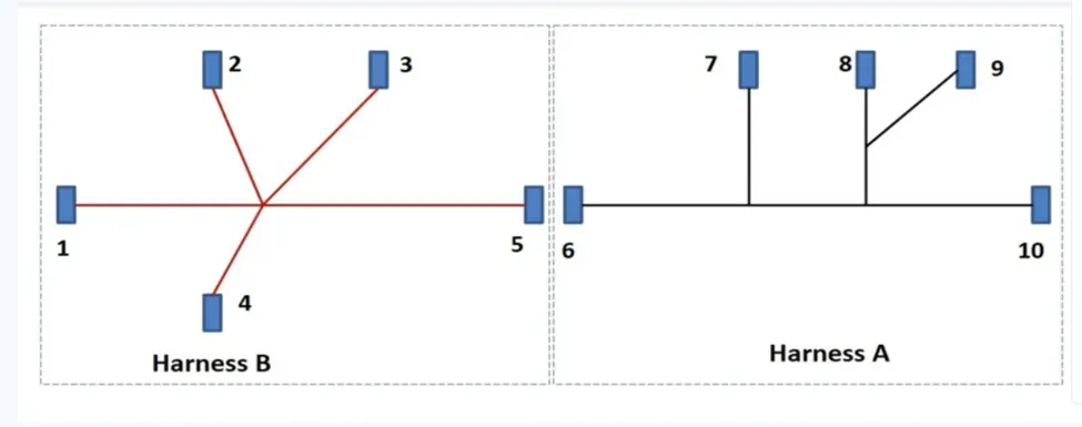
- Sketch the Branch of “Harness A” and “Harness B” by defining it as fully constrained as per given sketch on challenge.
- Save both file as “Sketch Harness A” and “Sketch Harness B”.
A) HARNESS A SKETCH
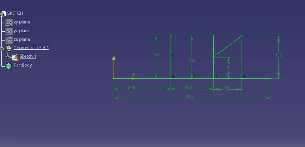
B) HARNESS B SKETCH
4. CREATE HARNESS A BRANCH ASSEMBLY
A) POSITIONING OF CONNECTOR
- Go to the “Assembly Design workbench”.
- Copy and paste all connector here.
- Also copy Sketch file of “Harness A” and “Harness B”
- Use “Smart Move” command and “Compass” for placing connector on desire position.
B) CREATE BRANCH BETWEEN CONNECTOR TO CONNECTOR
- Go to the “Electrical Harness Assembly workbench.
- Highlight “Product” from feature tree, then select “Geometrical Bundle” command then click on “Multi Branchable Document”.
- Click on “Branch Definition”, then “name” it and put the “Diameter” value and “Bend Radius Ratio” and “Slack (%)” value.
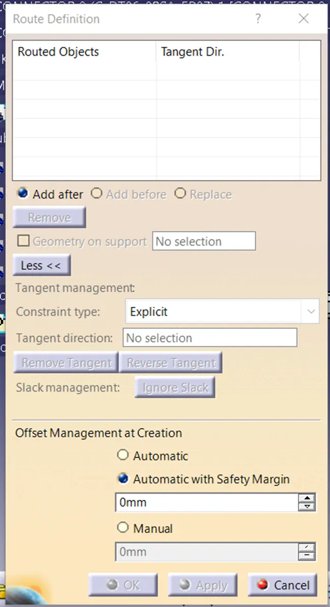
- Go to the Route Definition option.
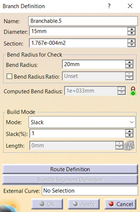
- Select first object then second object then click on ok.
- Give “Slack (%)” value according to smooth bend then click on ok.
- Choose “Reverse Tangent” as per required for smooth Branch connection and bending.
C) ADD BRANCH POINT
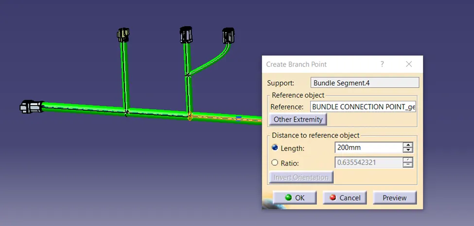
- Click on “add Branch Point” option.
- Select Branch then give the “Length” value, where Branch point is created then click on ok.
- Highlight “Product” from feature tree, then select “Geometrical Bundle” command then click on “Multi Branchable Document”.
- Click on “Branch Definition”, then “name” it and put the “Diameter” value and “Bend Radius Ratio” and “Slack (%)” value.
- Go to the Route Definition option.
- Select first object then select the Branch Point then click on ok.
- Give “Slack (%)” value according to smooth bend then click on ok.
- Choose “Reverse Tangent” as per required for smooth Branch connection and bending.
FOLLOW THE SAME TO CREATE BRANCH ON HARNESS B
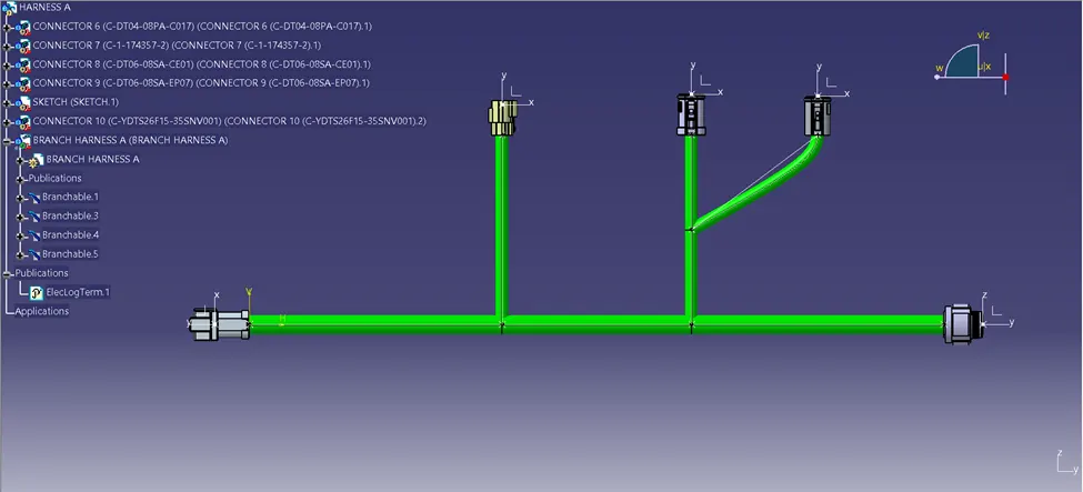
a) HARNESS A
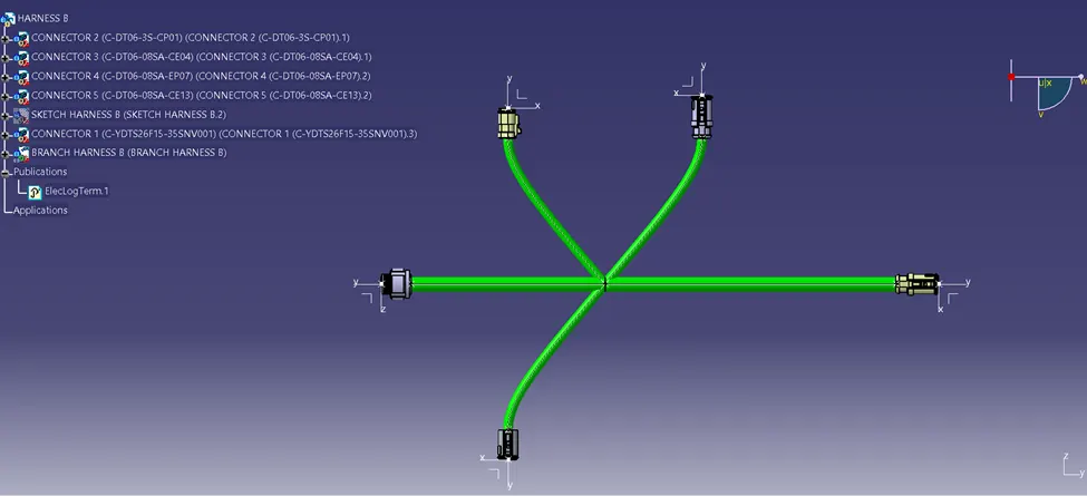
b) HARNESS B
5. CONNECT HARNESS A AND HARNESS B
A) POSITIONING
- Go to the “Assembly Design workbench”.
- Copy and paste “Harness A” and “Harness B” assembly file.
- Use “Compass” for placing “Harness A” and “Harness B” on desire position.
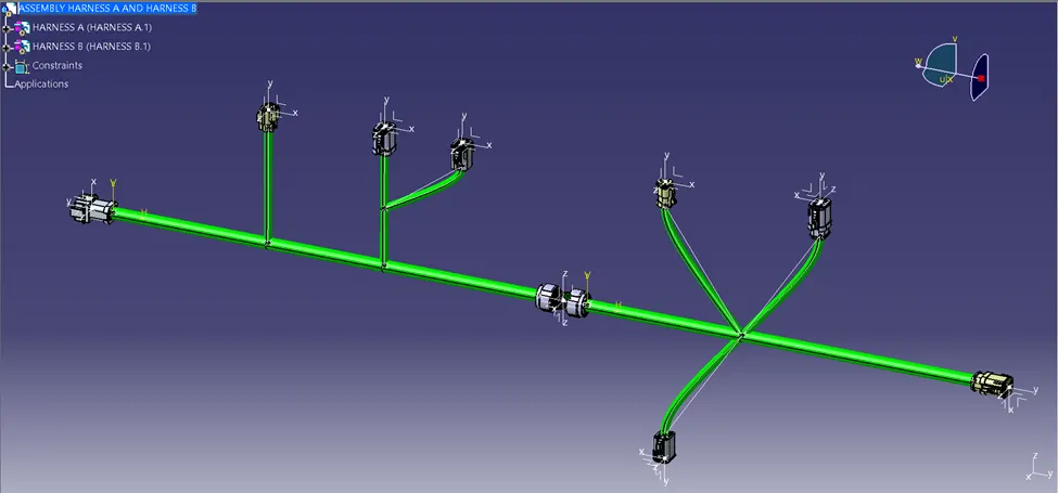
B) CREATE CONNECTION
- Go to the “Electrical Assembly Design” workbench.
- Select “Connect Electrical Devices”.
- Select “Connector Connection Point” of both Connector to connect.
- Then Click on Update. Both Connector is connected properly.
6. CREATE .CATPart FROM PRODUCT
- Open Assembly file in “Assembly Design” workbench.
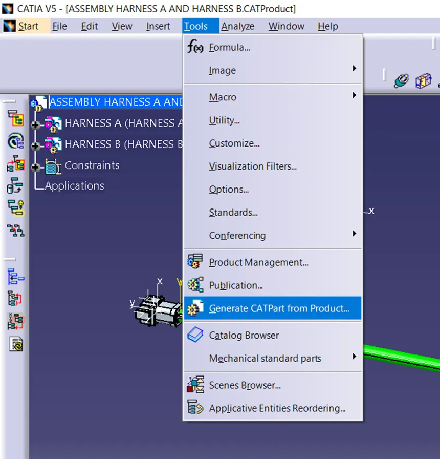
- Go to the “Tools” command.
- Select “Generate CATPart from Product…”
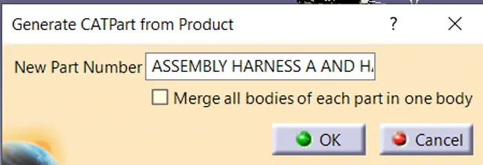
- Give “New Part Number”, then click on OK.
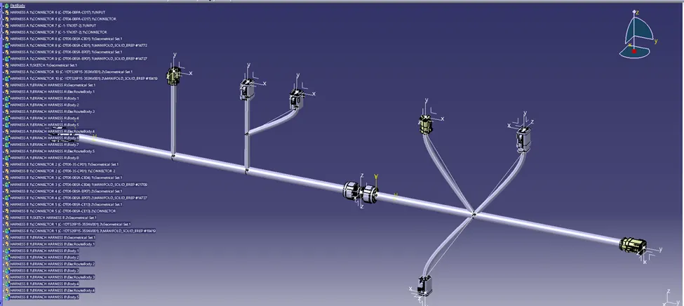
- “Product” file is automatically converted into “CATPart” file.
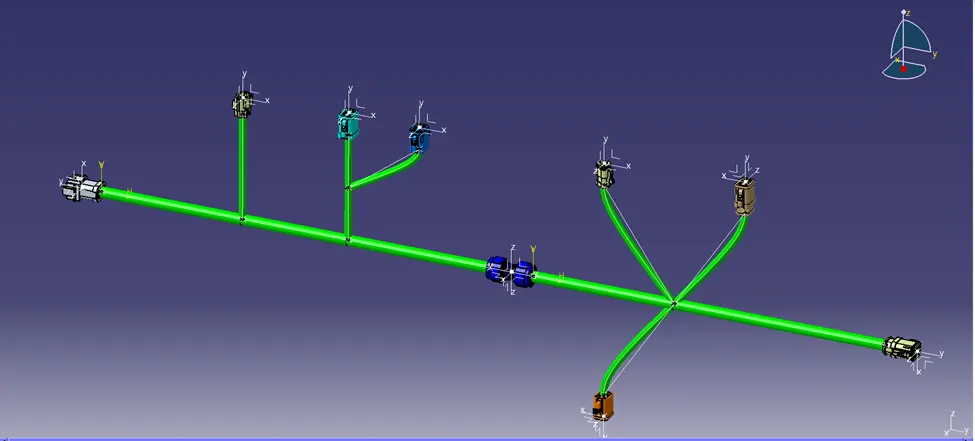
· Select Branch and Connector then choose “Properties” option and change the colour of the Branch and Connector.
· Save the “.CATPart” file.
7. CREATE .Igs FILE
- Go to “File” menu, Choose “Save as”.
- Select “igs” in “Save as type” option.
- Give the “File name”, then click on “Save”.
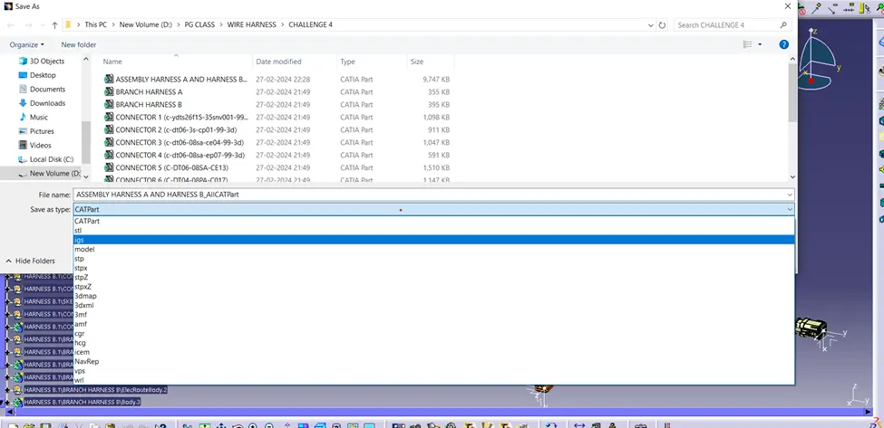
- “.igs” File is created automatically

8. REPRESENTATION OF BUNDLE WARNING
Bundle Warning can be find by various symbol and colour. By seeing this, we know the, modification is still pending for proper Wire Harness.
A) FEATURE TREE SYMBOL
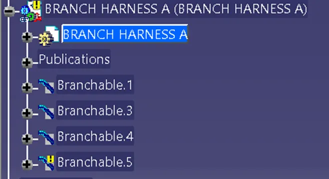
If wire harness of Branch is not done properly, then the “Geometrical Bundle” in “Feature Tree” represent in “Yellow Colour” with Exclamation Mark. So, that it is understood the Branch is not created properly and if multiple branch is extended from Feature Tree then Particular Branch is highlighted with this warning symbol.
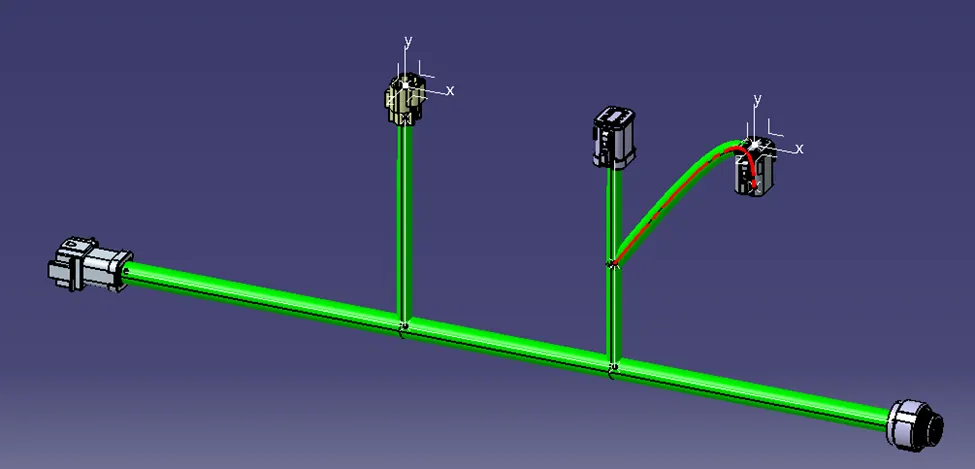
B) BRANCH SHOWN WITH RED COLOUR CENTER LINE
If wire harness of Branch is not done properly or Direction of branch is given in wrong direction, then the Branch shown with Red colour center line. Then modify it.
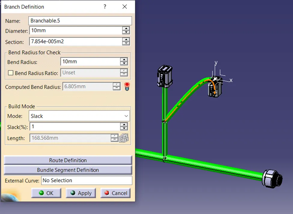
C) BRANCH DEFINITION RED SYMBOL
If wire harness of Branch is not done properly or Direction of branch is given in wrong direction or have bend radius or slack % value etc, then the Warning is shown with Red Colour symbol in Branch Definition and if there have no issue with branch wire harness then it show in Green Colour symbol.
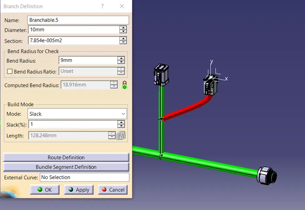
D) RED COLOUR OF BRANCH
If wiring harness is not done properly then the Branch is appear in Red Colour and if there have no issue in wire harness then it appear with Green colour. So, we can understand easily, that which one of the branch is not done properly.
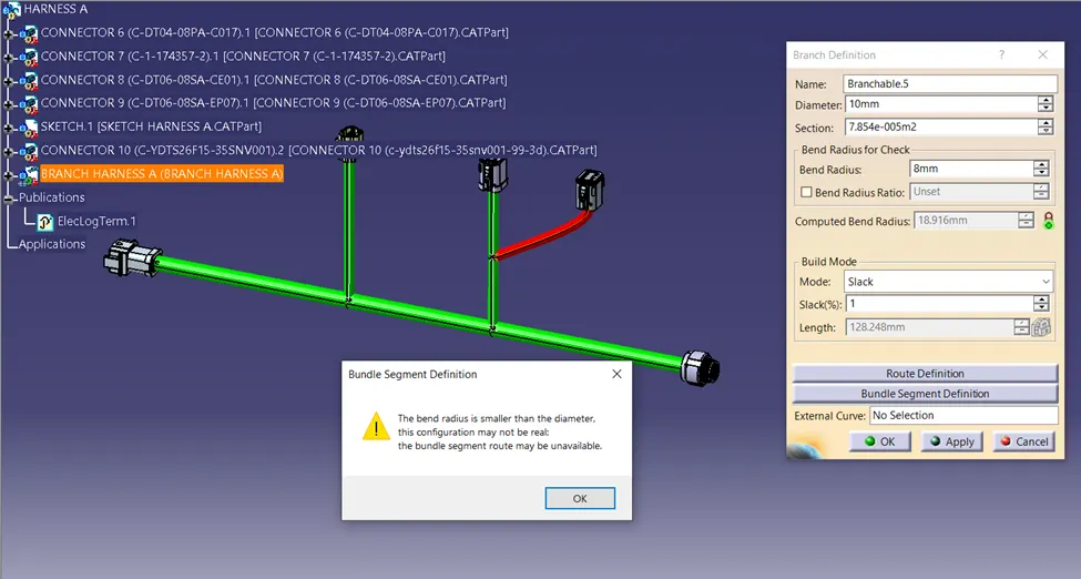
E) YELLOW FLASH WARNING
Sometimes Yellow Flash Warning is also appear with problem statement. And by this we know the actual problem of the Branch of wire harness and can resolved it.
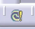
F) UPDATE
Wire harness warning also appear in update with exclamatory symbol and sometime after further modification, if update is not done then “Update” symbol is shown in Highlighted form. So, it is important to ensure the “Update” symbol is not highlighted.

9. SOLUTION OF BUNDLE WARNING
This is very important to check warnings when routing the wire harness, which is shown in feature tree of wire harness geometry and solved it by modifying some commands to create perfect branch. Before going forward, we should ensure all the branch placed properly in correct position.
A) BEND RADIUS
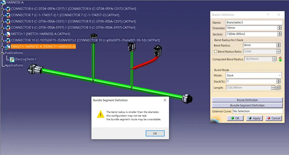
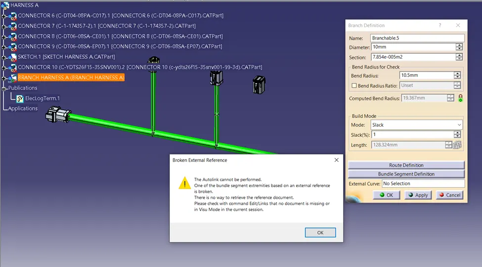
- Bend radius of branch is always same as bundle diameter.
- If “Bend Radius” is smaller than “Diameter”, then branch is showing warning and it appear in red colour.
- Check the “bend Radius” and then to ensure no warnings, modified it.
B) BUNDLE DIAMETER
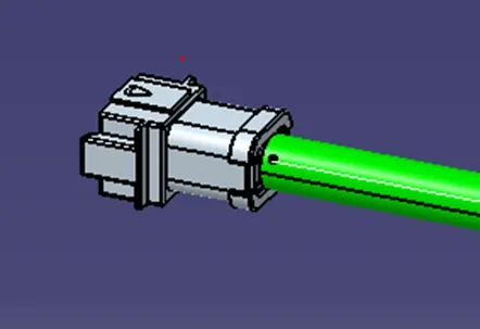
Bundle Diameter is given as per Connector size or we can say as per connector specification. The value of Bundle diameter is less than the Connector size.
C) SLACK %
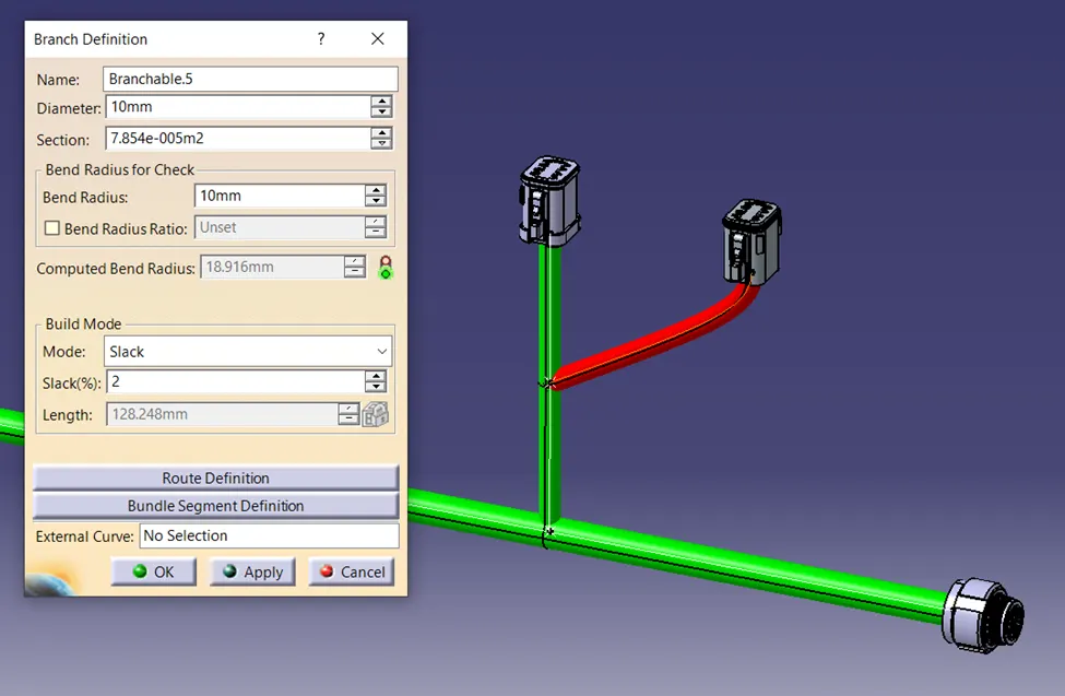
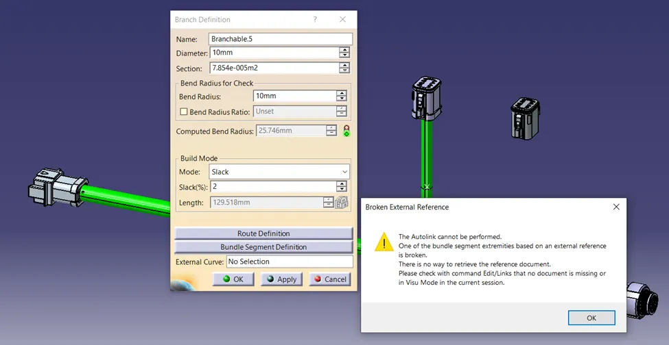
Slack % is necessary for smooth bending of Branch. It is given as the value of “Computed Bend Radius” is less than the double of diameter. If Slack % in increased and thus “Computed Bend Radius” value reach greater than double of “Bend Radius” than it show warning and also Branch is deleted automatically.
D) TANGENT
Direction of Branch is also given properly for proper Wire Harness. If Direction is not properly given then warning is shown and the center line of branch is appear in “Red Colour”. For proper wiring harness, select “Reverse Tangent” option, then apply.
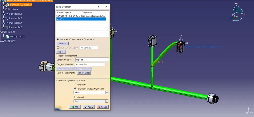
E) LENGTH OF BRANCH
If length of branch is too short then also it show warning. To resolve this problem
- Increase the distance of branch by moving connector.
- By moving “Branch Point”. Distance between connections by giving Branch start point and end point position.
- Move the clip position, if it placed.
- Move the component position.
- By rotating clip orientation.
F) LINK AND UNLINK
- Link and Unlink command is used to create a proper position of branch.
10) 3D ANNOTATION
- 3D Annotations bring you a more efficient and accurate noting in 3D mode for precision, accuracy, and a better experience when annotating your model.
- Annotations in 3D will snap right onto the 3D surface and draw exactly where your cursor is pointed, allowing you to make the most accurate measurements ever in 3D.
- This will enable you to precisely measure complex 3D structures such as towers, buildings, and facilities.
- This is used to show connector function and additional notes that needs to be review during manufacturing review or service availability review etc.
- It is a way to represent the data or information in quicker way.
A) CONNECTOR FUNCTION ANNOTATION
- Connector Function Annotation is used to represent the properties of connector.
- It is used to the connector to show the function of the connector.
- It is very helpful to represent the drawing to anyone to understand.
- Connector annotation is an on-screen direct connection line between two nodes of the diagram.
- It supports simple conflict resolution. If multiple connector annotations overlap each other between the same pair of nodes, the control offsets them and draws them parallel.
- Can give the information regarding Sealed or Unsealed Connector, resistor, mating side etc.
B) WIRE HARNESS DARWING NOTE
- This is used to add the harness data to show specific information relating to the harness i.e. wire type, wire specification.
- Any additional information/comment can be shown by wire harness drawing note.
C) PROCEDURE
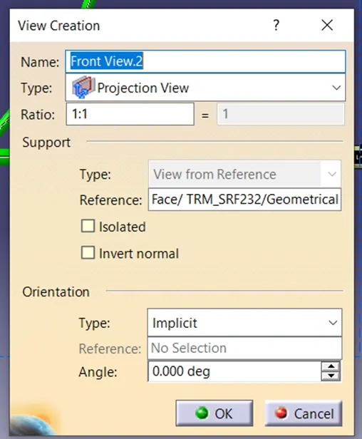
a) VIEW FROM REFERENCE
- Go to the “Assembly Design” workbench.
- Select “View from Reference” then choose “Front View” in “Tool Pallets” option.
- Select the face or plane.
- Give all parameter value then click on ok.
b) FLAG NOTE WITH LEADER/ FLAG NOTE
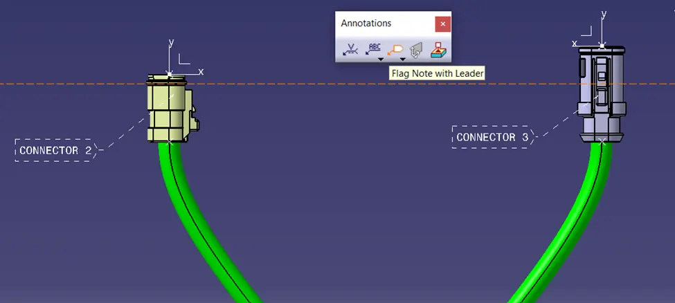
“Flag Note with Leader” is used to represent the Name, Identification, Numbering, etc for any component or branch. This is shown as arrow with extension line.
- Go to the “Assembly Design Workbench”.
- Go to the “annotations” toolbar and select “Flag note with Leader/Flag Note” then select component.
- Name it then click on ok.
- Adjust the position of Note.
c) TEXT WITH LEADER/TEXT/TEXT PARALLEL TO SCREEN
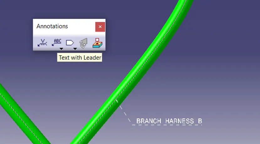
“Text with Leader”, “Text” and “Text Parallel to Screen” in which represent the “Detail Specification” for any component or assembly.
- Go to the “Assembly Design Workbench”.
- Go to the “annotations” toolbar and select “Text with Leader/Text/Text Parallel to Screen” then select component.
- Write the text then click on ok.
- Adjust the position of Note.
d) WELD FEATURE
“Weld Feature” is used to represent the Weld symbol, name etc.