Wiring harness design in CATIA V5 - 3D modeling Week 5 & 6 Challenge
Objective :
Q1. Route the following harness layout in Electrical workbench. Make assumption for harness bundle diameters. Use the connectors provided. After completion of routing,
- Check the bundle Continuity. Add snap of result in submission
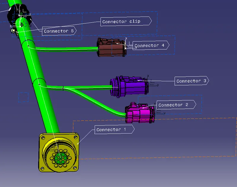
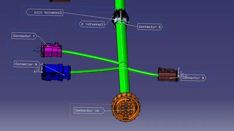
- Add annotation to all connectors. Make an assumptions for annotations like connect 1 , 2 etc
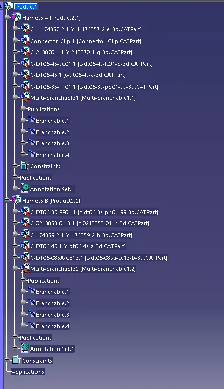
- Check for the bundle warning. Add snap.
- Generate CAT.part of harness assembly and convert is in. igs format.
Asnwers :
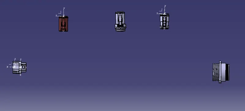
Placed all connectors of harness A in position .
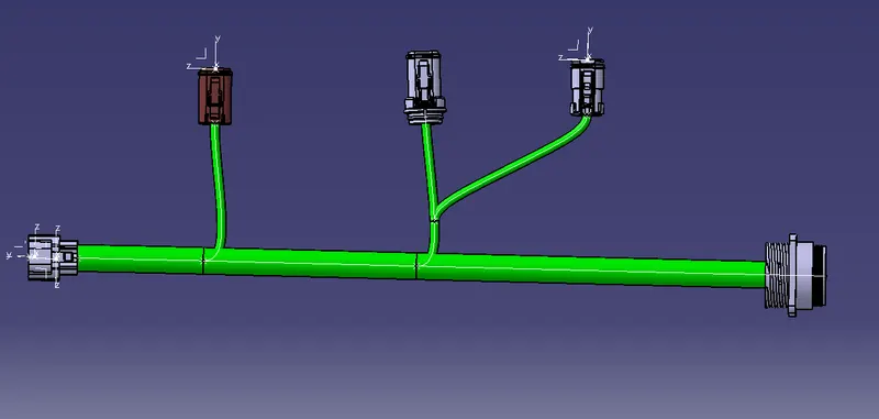
Used wiring harness installation workbench to create bundle segments as per given images .
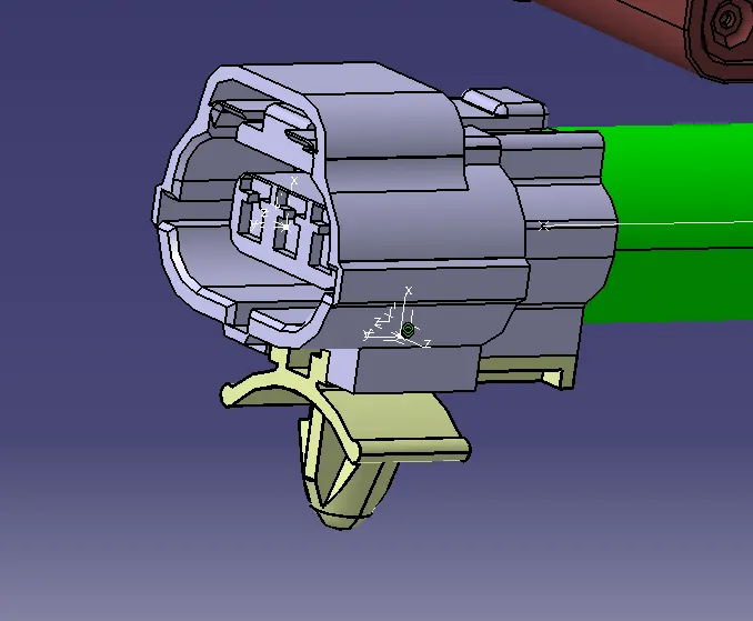
Connected the connector clip to connector using connect electrical devices command .
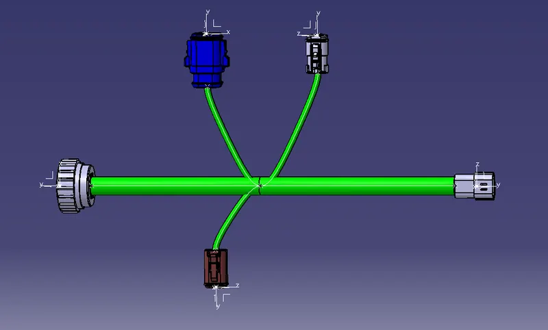
Similarly positioned and created bundles for harness B .
Added both harness A and B into a Product file . used connet electrical devices to connect male and female connector from harness A and B .
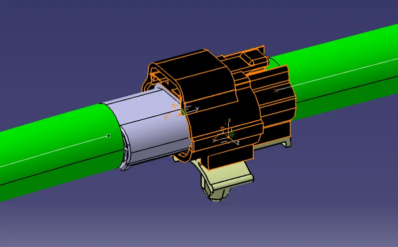
Now we have created and linked harness A and B .
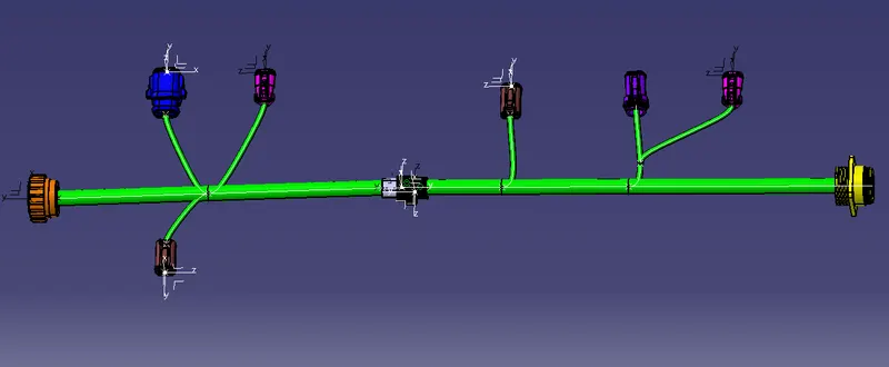
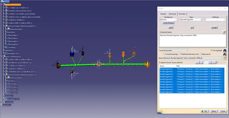
1. To check for bundle continuity , used search option from edit tab .
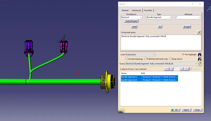
When we check with FALSE condition , we can see that there are 2 segments which are not fully connected . This is because there is no direct link between them .
2. Annotations
3. Bundle warnings
There are no yello icon near any of the branchables, hence there are no bundle warnings
4. catpart IGS file attached along with part files .