Wiring harness design in CATIA V5 - 3D modeling Week 5 & 6 Challenge
Week 5 & 6 Challenge
AIM:
To facilitate the routing of the harness layout within the Electrical workbench, it is essential to adhere to the specified conditions while utilizing the provided connectors.
OBJECTIVES:
- Check the bundle Continuity.
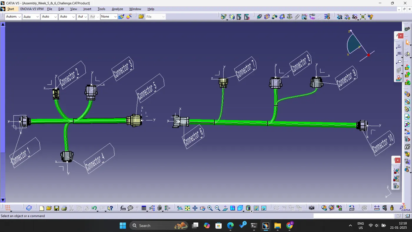
- Add annotation to all connectors.
- Check for the bundle warning.
- Generate the CAT.part of harness assembly and convert it in. igs format.
PROCESS:
1. Navigate to the Part Design Workbench and identify the central point of both the connector connecting side and the bundle connecting side.
2. Determine the axis origin at the connector connecting point.
3. Adjust the y-axis to be perpendicular to the face of the connector connecting point; designate the x-axis as the locking side, and establish the z-axis for vertical orientation, indicating either upward or downward direction.
4. Subsequently, transition to the Electrical Part Design Workbench, where you will define the component as a connector. Specify the number of terminals it contains and accurately represent both the connector connection point and the bundle connection point concerning their respective faces and representations.
5. Similarly follow the same process for all the connectors provided in this challenge.
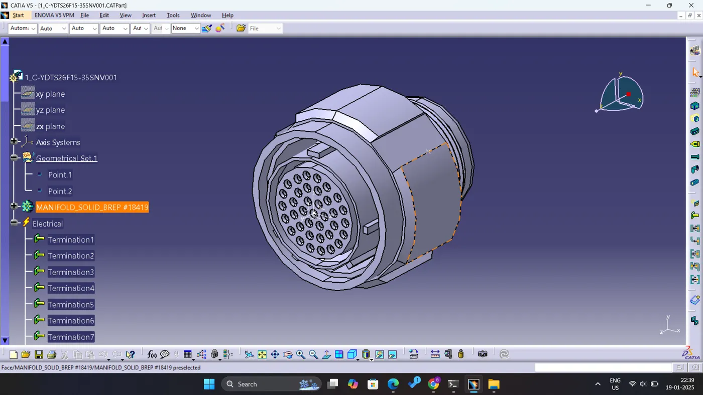
Fig: Connector 1
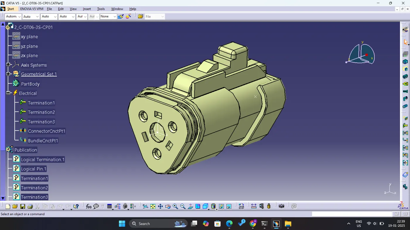
Fig: Connector 2
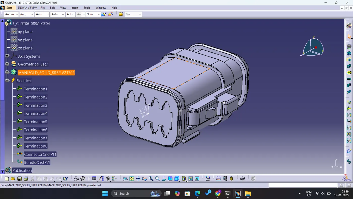
Fig: Connector 3
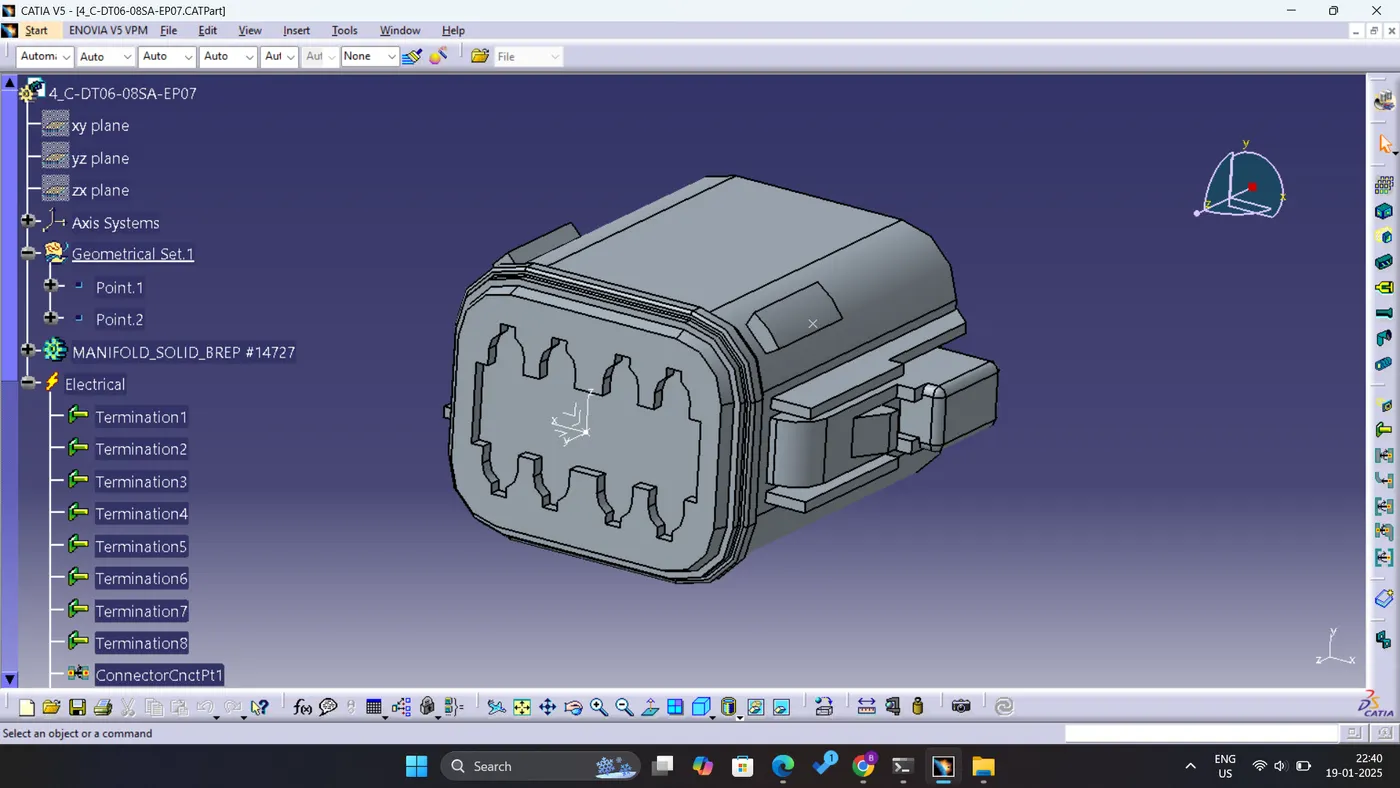
Fig: Connector 4
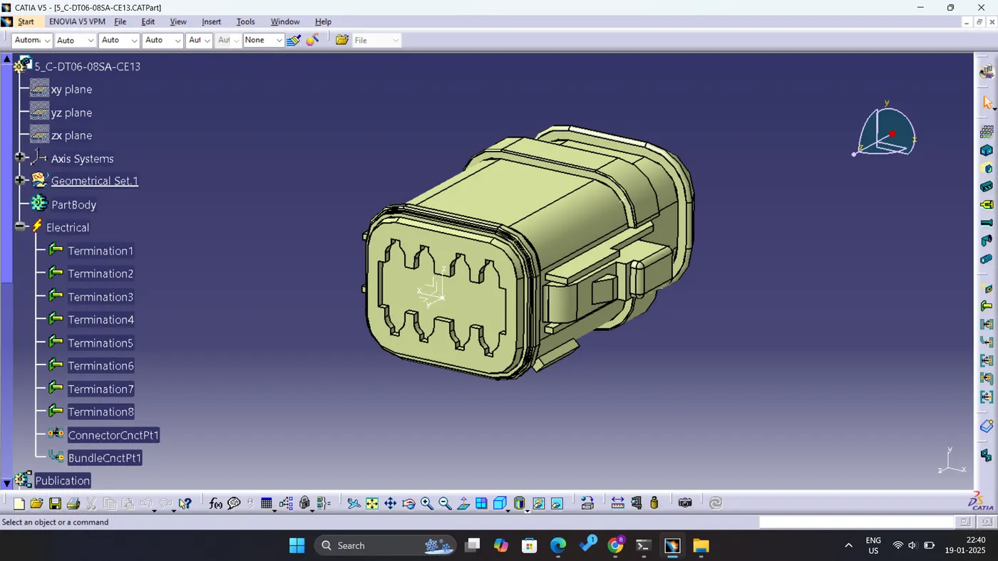
Fig: Connector 5
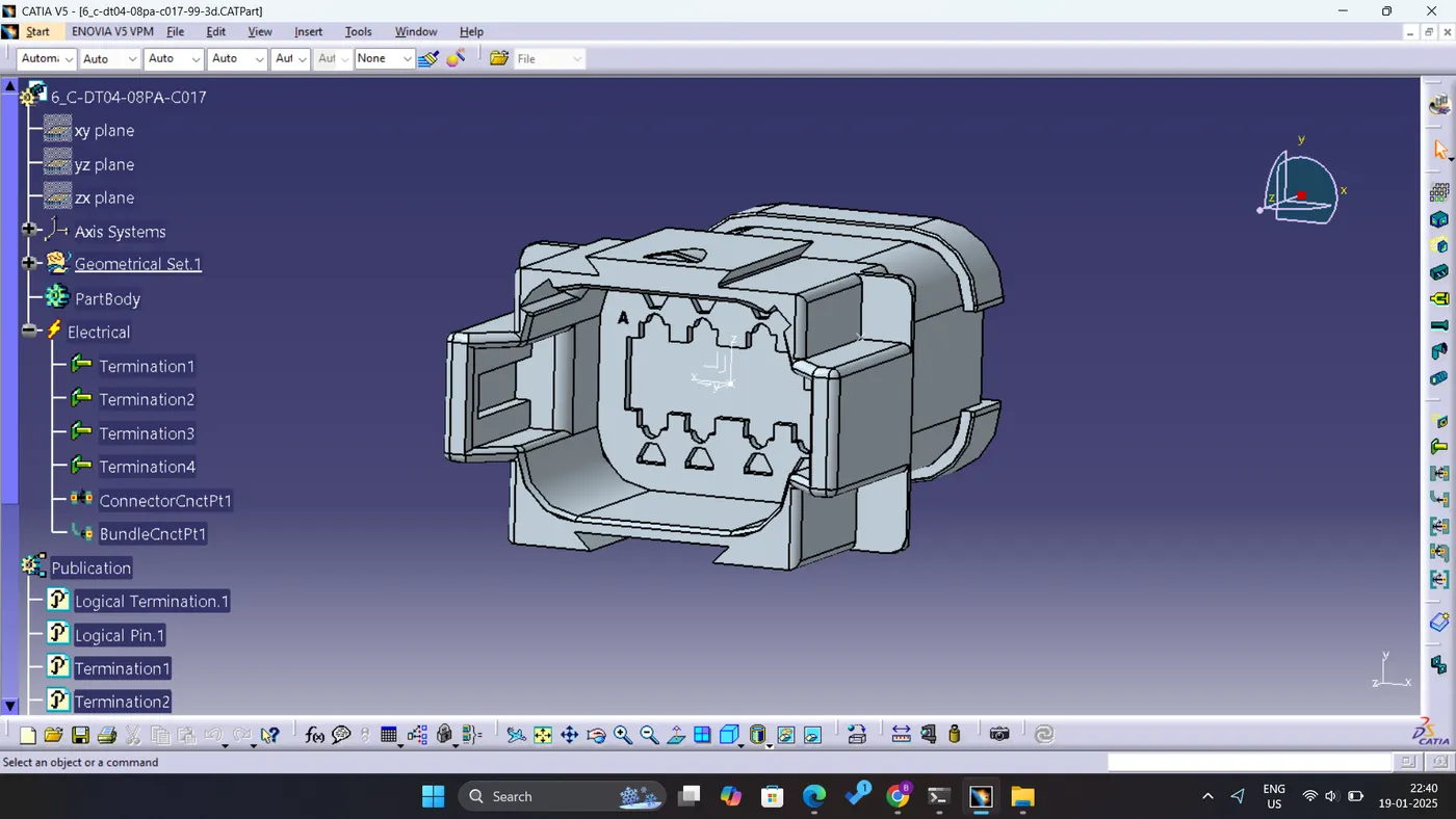
Fig: Connector 6
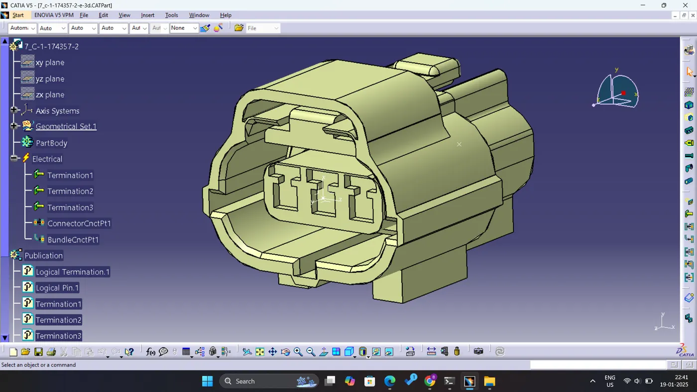
Fig: Connector 7
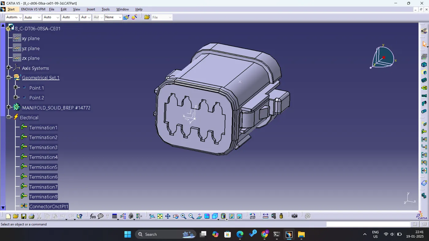
Fig: Connector 8
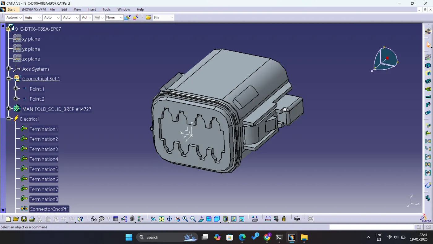
Fig: Connector 9
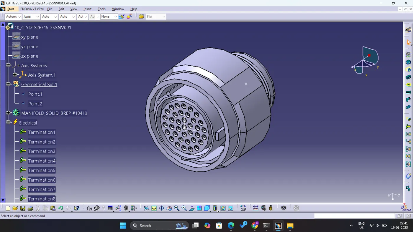
Fig: Connector 10
HARNESS A:
Proceed to the electrical harness assembly and classify the product as a geometric bundle. Subsequently, navigate to the multi-branchable point to route the bundles and determine appropriate breakpoints following the diagram.
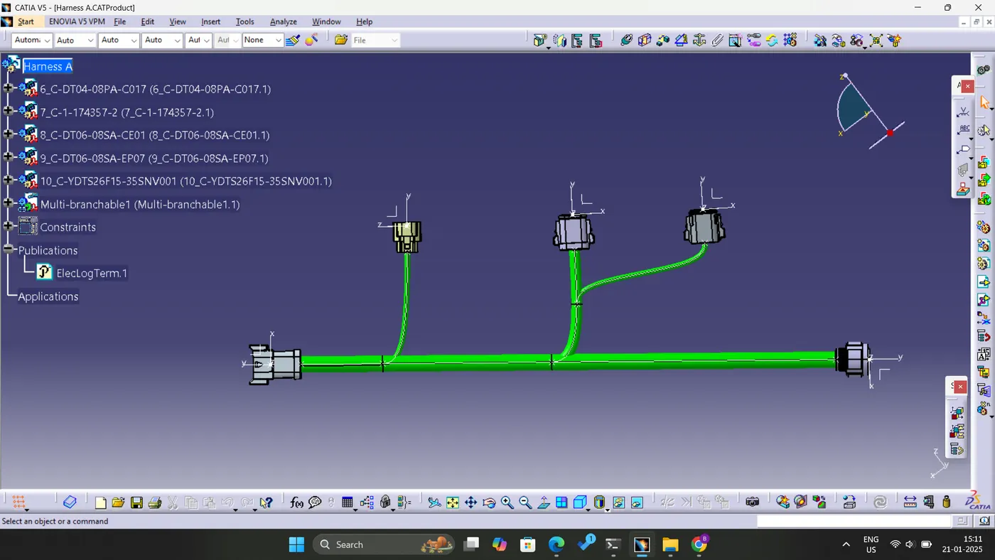
Fig: Harness A
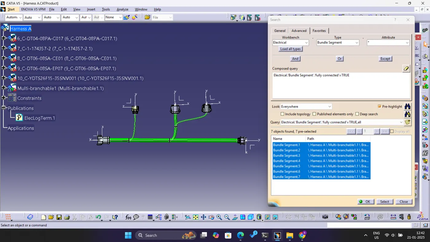
Fig: Bundle Continuity of Harness A
HARNESS B:
Proceed to the electrical harness assembly and classify the product as a geometric bundle. Subsequently, navigate to the multi-branchable point to route the bundles and determine appropriate breakpoints following the diagram.
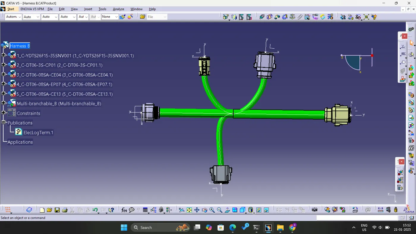
Fig: Harness B
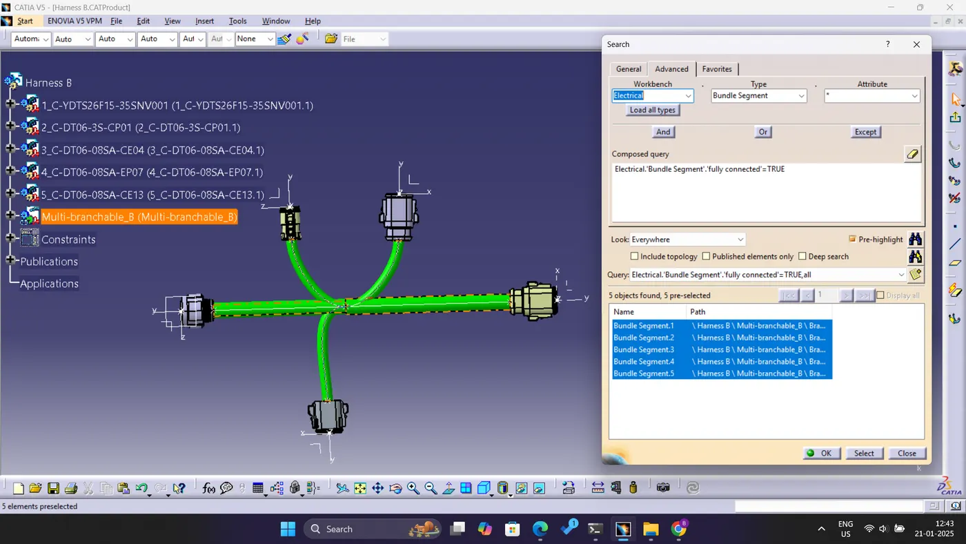
Fig: Bundle Continuity of Harness A
ASSEMBLY OF HARNESS A AND HARNESS B:
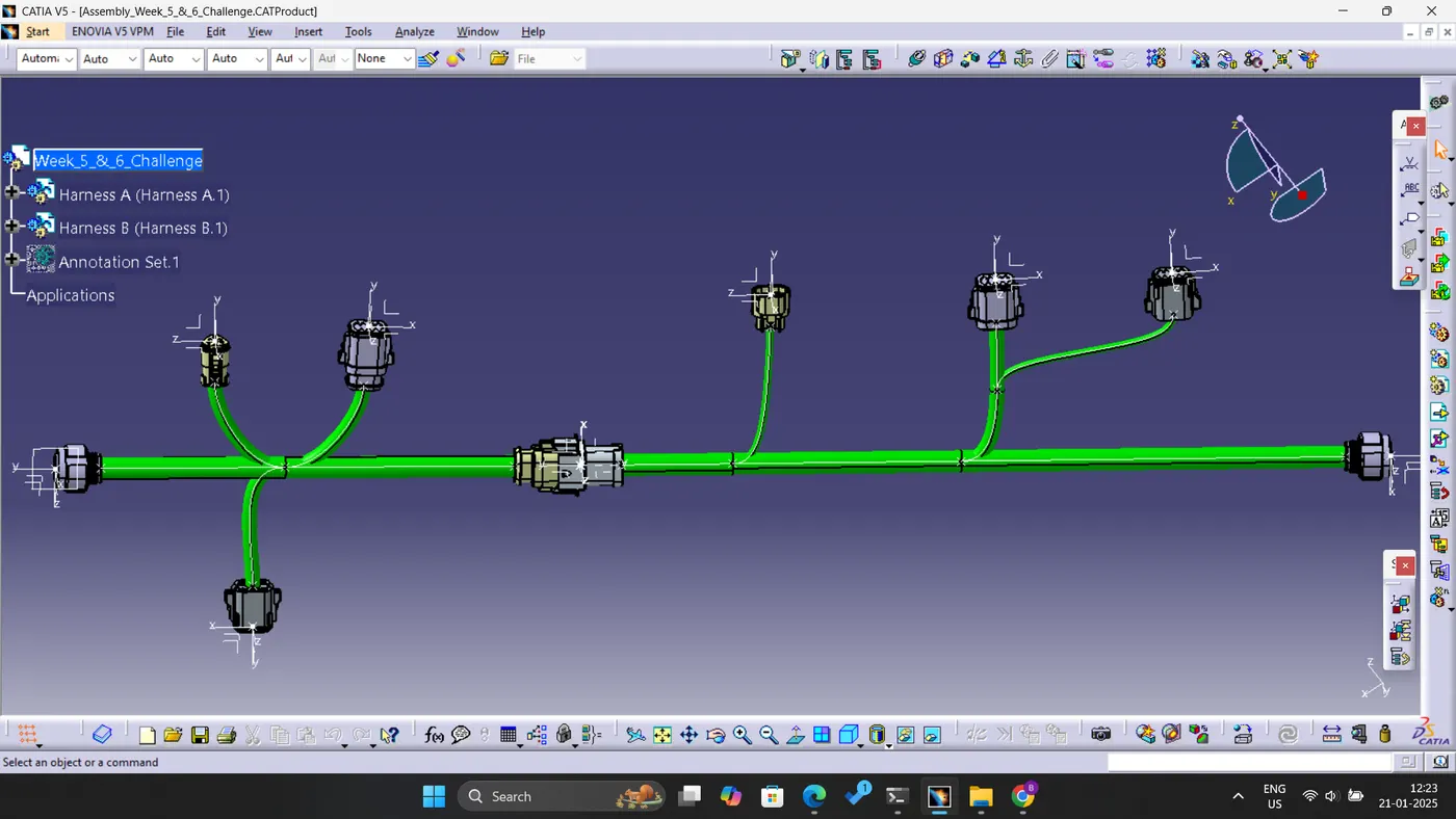
Initially, Harness A and B were positioned within the Electrical Assembly Workbench and attempted to connect them; however, the connection was not established effectively, as illustrated in the accompanying figure. Following an update of the components, a proper connection was successfully achieved.