Wiring harness design in CATIA V5 - 3D modeling Week 5 & 6 Challenge
Q1. Route the following harness layout in Electrical workbench. Make assumption for harness bundle diameters. Use the connectors provided. After completion of routing,
- Check the bundle Continuity. Add snap of result in submission
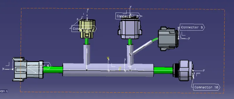
- Add annotation to all connectors. Make an assumptions for annotations like connect 1 , 2 etc
- Check for the bundle warning. Add snap.
- Generate CAT.part of harness assembly and convert is in. igs format.
Click here for CAD data and routing mapping data
Ans:
STEP1:
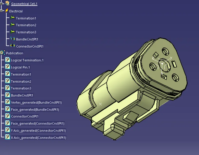
Download the connector files and define all the connectores electrically
Provide the axis and point as per the requirement, then
Define Bundle connection point and conncetor connction point using electrical part design for all conncectors
STEP2:
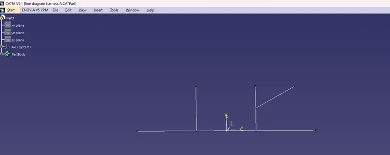
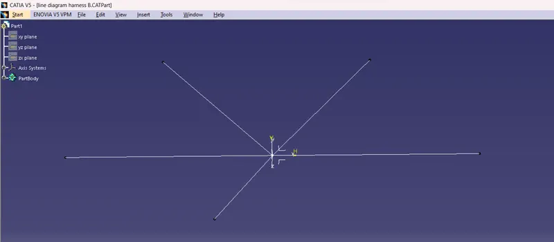
SKETCHING THE LINE DIAGRAM: Go to the file select new and then select part. In the part select any plane and draw the sketch a as per above image.save the sketch create for both harness A and B
STEP 3:
Import all conncectors and line diagram to a new Product design and allign them properly (for both A and B)
STEP 4:
Switch to electrical harness assembly ---> select geometric bundle --->slelect on product(top left) ---> select multibranchable document --->route definition ---> select first and last part ---> click ok
so conncetions are created and new conncetions repeat the same process
For creating branch point: add branch point ---> select the lenth and extremity --> click ok
toa dd cot tube: select protective harness covering in the electric harness work bench
STEP 5:
Go to Assembly design work bench ---> select Add Flag note with leader ---> select the desired axis for proper allignment
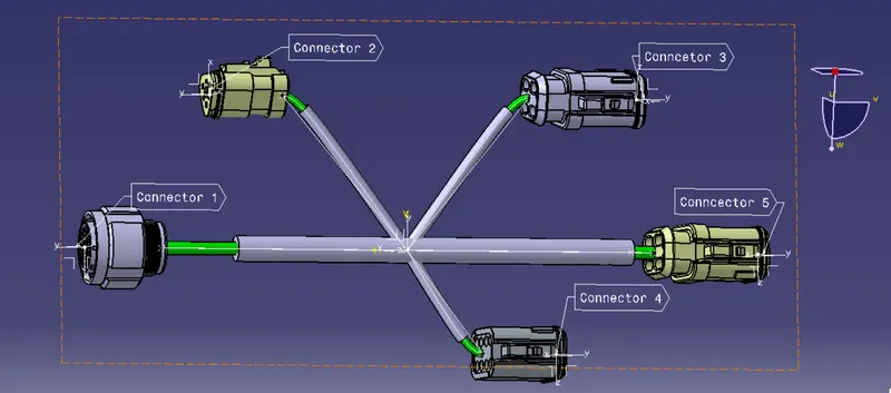
STEP 5:
To convert to igs format select save as and change the format before saving