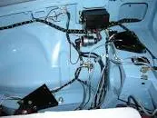
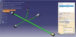
Wiring harness design in CATIA V5 - 3D modeling Week 5 & 6 Challenge
REPORT WRITING:
-
Project Overview: The harness layout was developed as part of which involves the electrical integration of the objective was to design an efficient and reliable harness that meets all electrical and mechanical requirements.
-
Harness Layout Description: The harness layout was created using the Electrical Workbench software, which offers comprehensive tools for designing and documenting electrical systems. The following key elements were considered during the layout process:
a. Harness Routing: The routing of the harness was planned meticulously to ensure optimal placement within the system. Factors such as length, bend radius, and accessibility for maintenance were taken into account.
b. Component Positioning: The positioning of electrical components within the harness was determined based on functional requirements, space constraints, and ease of installation. Special attention was given to minimizing interference and maintaining proper clearances.
c. Connector Selection: Suitable connectors were chosen to establish reliable electrical connections between components. Factors considered include current rating, environmental conditions, and compatibility with the associated components.
d. Wire Selection: The selection of wires was made in accordance with relevant standards and specifications. Factors such as voltage rating, current carrying capacity, and insulation properties were considered to ensure safe and efficient operation.
e. Protective Measures: Proper measures were implemented to protect the harness from potential hazards, including abrasion, vibration, heat, and moisture. Protective sleeves, loom tapes, and conduit routing were utilized as necessary.
f. Labeling and Documentation: Each wire, connector, and component within the harness was appropriately labeled for easy identification and troubleshooting. Detailed documentation, including wiring diagrams and bill of materials, was generated using the Electrical Workbench software.
-
Compliance with Standards and Regulations: The harness layout was designed to comply with all relevant industry standards, codes, and regulations. These include but are not limited to [List applicable standards/regulations]. Compliance ensures that the harness is safe, reliable, and meets the necessary performance requirements.
-
Future Considerations: As part of ongoing improvement, the following considerations were made for future revisions or modifications to the harness layout:
a. Flexibility: The harness layout allows for future expansions or modifications to the system without requiring significant redesign. Extra connectors or wires were incorporated to accommodate potential changes.
b. Serviceability: Accessibility to individual components and connectors was prioritized to facilitate ease of maintenance, repair, or replacement, reducing downtime and associated costs.
-
Conclusion: The harness layout created using the Electrical Workbench software provides an optimized and efficient solution for the electrical integration of [System/Equipment/Component]. It meets the necessary electrical, mechanical, and safety requirements, ensuring reliable operation and ease of maintenance.
Assuming you are referring to the diameters of harness bundles used in electrical wiring and using standard connectors, here are some general assumptions:
-
Wire Gauge: The wire gauge commonly used for automotive and industrial wiring ranges from 18 AWG (0.823 mm) to 10 AWG (2.588 mm) for general-purpose applications. However, larger diameters may be used for high-power or specialized applications.
-
Connector Types: Depending on the specific connectors provided, the wire bundle diameters may vary. Common connector types include circular connectors, rectangular connectors, and modular connectors, each with different accommodation capacities.
-
Connector Accommodation: The connectors you have available may have specified maximum diameters or maximum wire bundle sizes they can accommodate. It is crucial to consult the connector datasheets or specifications to determine the appropriate wire bundle diameter.
-
Expansion and Flexibility: When routing a harness, it is common practice to leave some additional space for expansion, strain relief, and flexibility. This additional space ensures that the wires can move without being excessively stretched or strained. Typically, an extra 10-20% of the wire bundle diameter is allowed for expansion and flexibility.
Once you have routed the harness and determined the appropriate wire bundle diameters based on the connector specifications and allowances for expansion, you can proceed with reporting the details of the harness. In the report, you would typically include:
-
Harness Identification: Provide a unique identifier or name for the harness, including any relevant project or system information.
-
Wire Gauge and Colors: Specify the wire gauge (AWG) used in the harness, along with the corresponding color codes. This information helps identify and trace individual wires within the harness.
-
Connector Types and Locations: Document the specific connector types used in the harness, along with their locations within the system. This information aids in installation, troubleshooting, and future maintenance.
-
Wire Bundle Diameters: Report the determined wire bundle diameters after considering the connector specifications and allowances for expansion. Include the exact diameters or size ranges for each wire bundle segment.
-
Routing Diagram: Provide a visual representation or diagram illustrating the routing path of the harness. This diagram should indicate the connector locations, wire bundle diameters, and any notable routing considerations.
-
Additional Notes: Include any additional information or observations relevant to the harness, such as specific routing challenges, special requirements, or any deviations from standard practices.
By providing a comprehensive report on the harness, you ensure clear documentation and facilitate future reference, maintenance, and modifications.