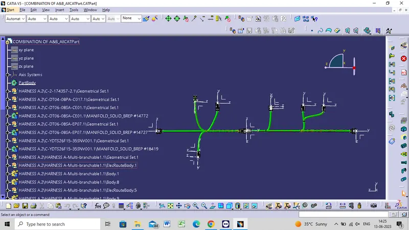
Wiring harness design in CATIA V5 - 3D modeling Week 5 & 6 Challenge
AIM
Route the two electrical harnesses as per the given layout and interconnect them as a single harness assembly and then check for bundle continuity, bundle warnings, and then give annotations to the final harness assembly.
STEP TO DEFINE ELECTRICAL
- Create midpoint on the contact face which will be normal to wire bunddle insertion.
- Create Axis System with respect to the point which we have created and defining the axis direction as shown below
- Define connector
- Define Connector connection point
- Define Bundle connection point
CONNECTOR 1
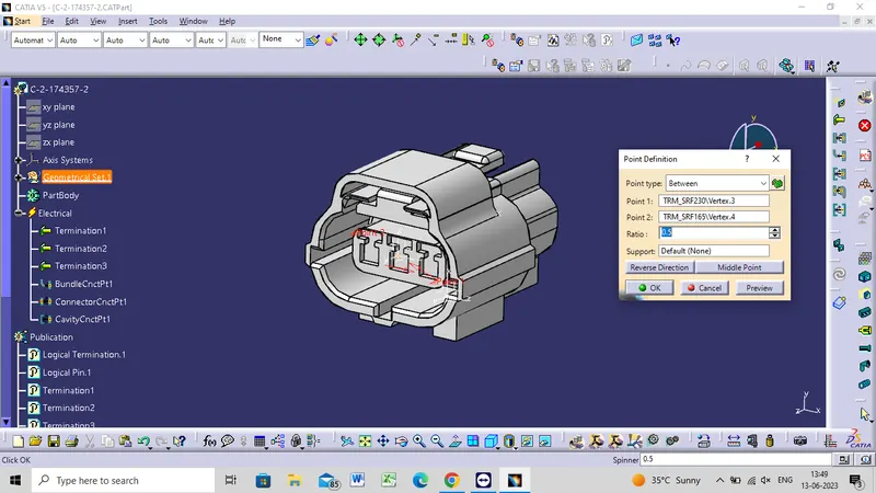
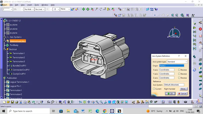
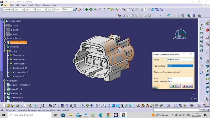
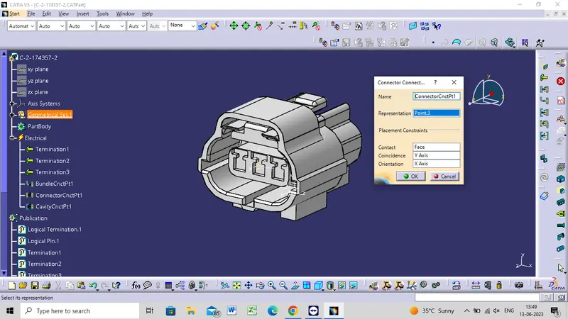
CONNECTOR 2
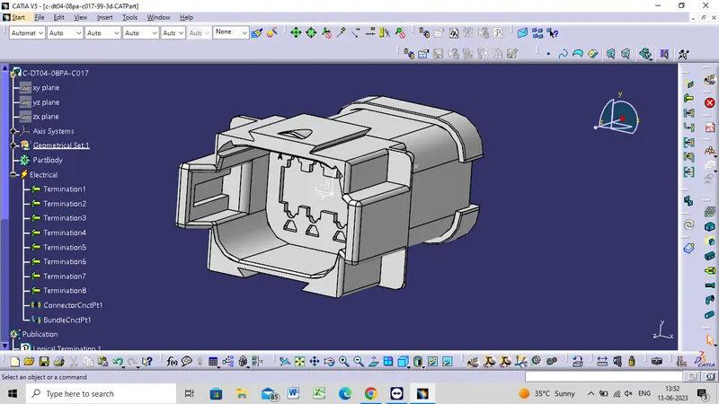
CONNECTOR 3
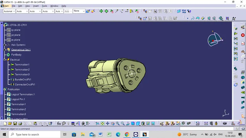
CONNECTOR 4
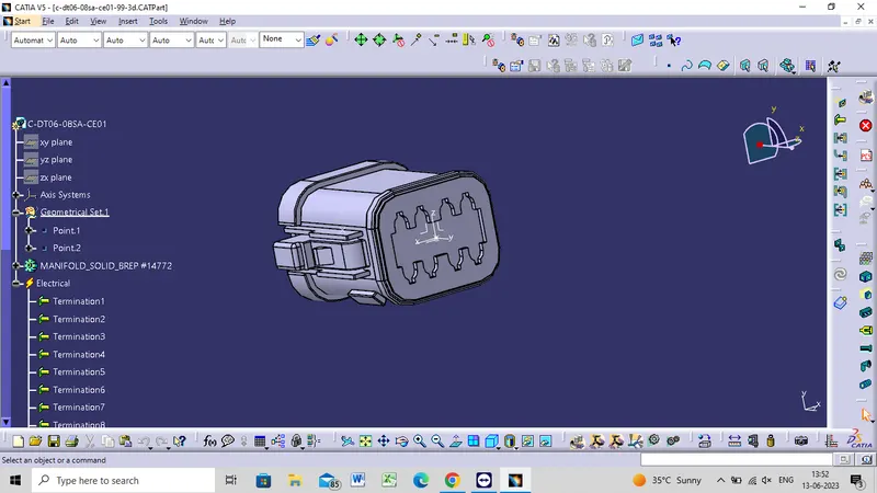
CONNECTOR 5
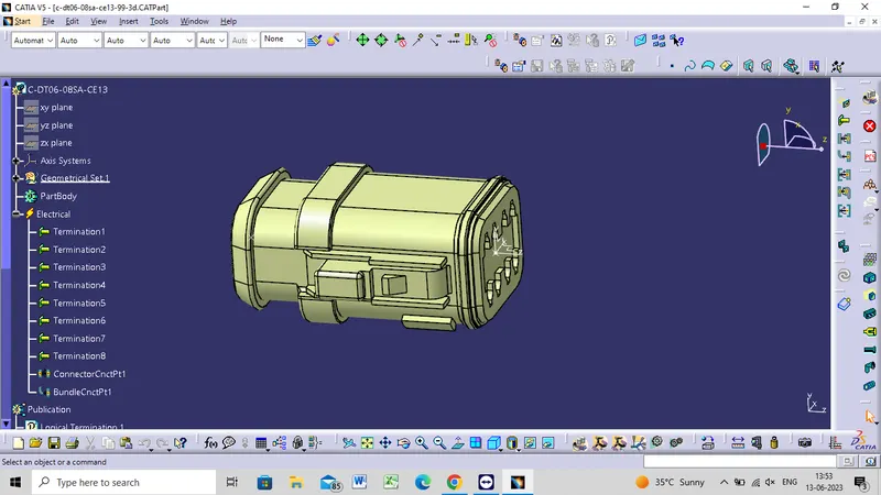
CONNECTOR 6
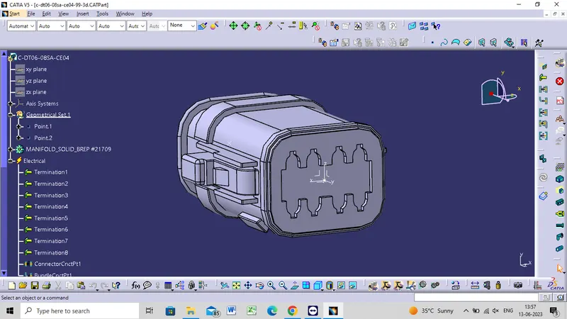
CONNECTOR 7
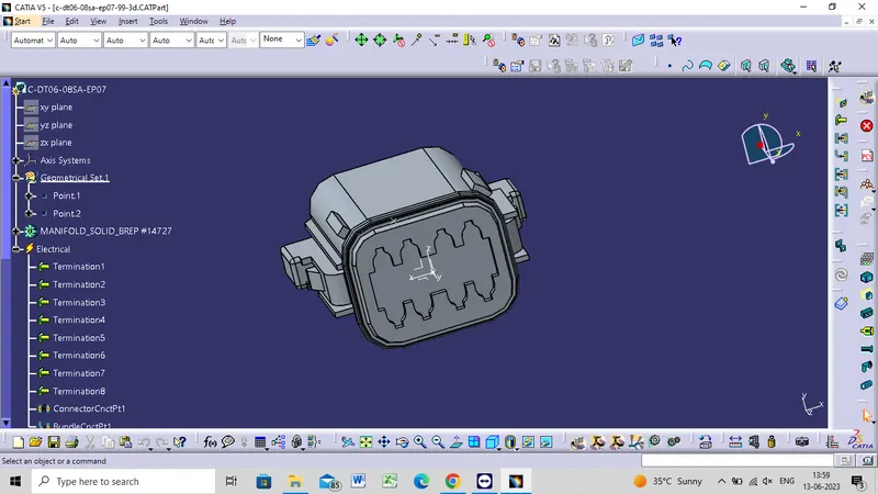
CONNECTOR 8
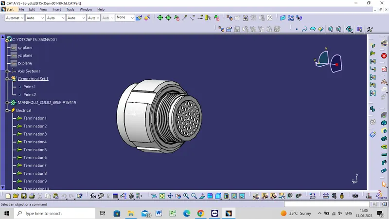
CONNECTOR 9
CONNECTOR 10
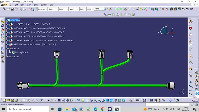
HARNESS A
- All the connectors are defined, the workbench was switched to Electrical Harness Assembly and Geometrical Bundle was activated.
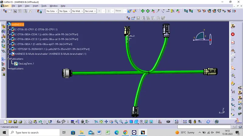
- All the connectors were routed using the Multi-Branchable command.
HARNESS B
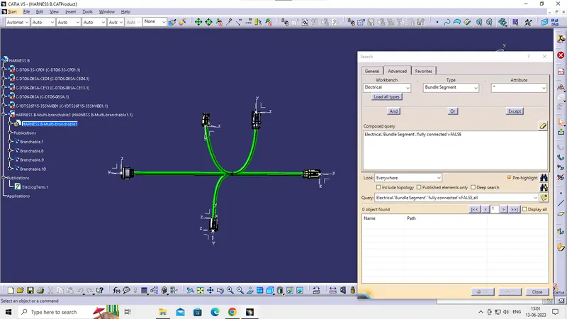
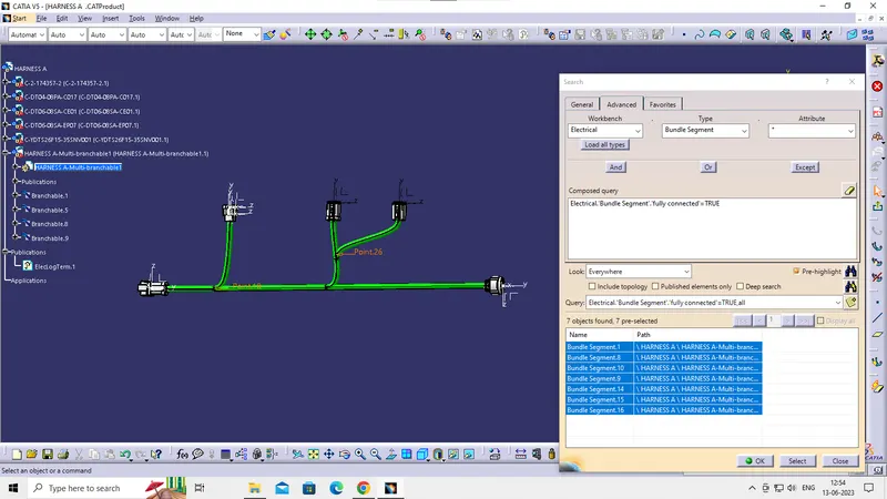
CONNECTIVITY CHECK
HARNESS B
HARNESS A
HARNESS ASSEMBLY
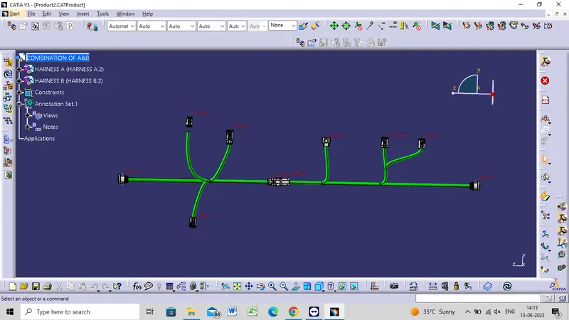
- In this step, we have to interconnect both Harness A & Harness B.
- For that, we have to create new product file and can give name as Assembly.
- Then, copy both harnesses and paste it in newly created product file or call both harnesses in mechanical assembly design as below image.
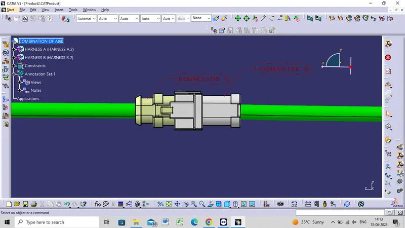
- We have to go in Electrical Assembly Design to connect both the harnesses electrically. So for that, select the option 'connect electrical devices'
and both the harnesses will get connected electrically as below. - As shown in below image, male connector should have to be inserted into the female connector.
ANNOTATIONS
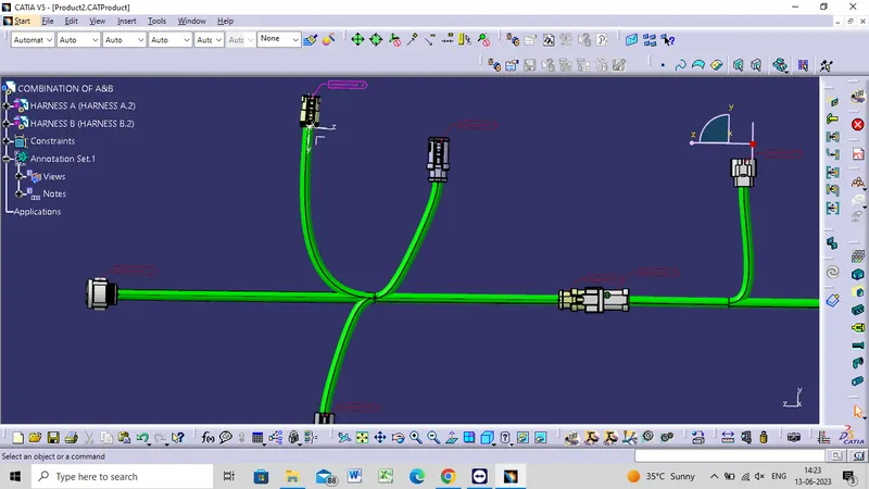
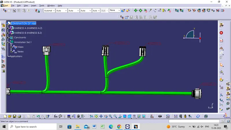
- In this step, we have to add annotations for all the connectors in mechanical assembly design workbench
- Annotations are used for giving connector name, functions etc.
- For this, we have to select plane where annotation will be placed. In below image, we have selected front plane.
- We should make sure that the geometrical bundle is active before selecting the annotation plane.
- We can change a font, font color and font size by going into the properties as shown in below image.
CONVERTING TO CAT PART
- Now, in this step we have to convert final harness assembly file into IGS format. So for that we need to follow below steps.
- Mechanical Assembly Design workbench>Tools>Generate CAT Part from product.
- Once the CAT part is created, the whole product file is converted into a single part.
- Now, whole file is converted into the IGS format and we can see all the harness assembly is looking in grey color.
- If we need to change color as before in green, we can go back and give green color to each bundle segment.