Wiring harness design in CATIA V5 - 3D modeling Week 5 & 6 Challenge
Route the following harness layout in Electrical workbench. Make assumption for harness bundle diameters. Use the connectors provided. After completion of routing.
- Download all the CAD files and define them as electrical devices appropriately.
- Create a New Product File and name it as 'Assy_Wiring_Harness_routing_context'.
- Create two new product Files under the first product viz. Harness A and Harness B.
- Import all the CAD files into the product files and place them as defined in the diagram.
- Create a wiring harness using Branchable documents.
1. Check the bundle Continuity.
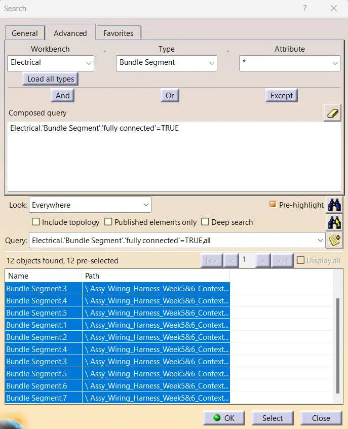
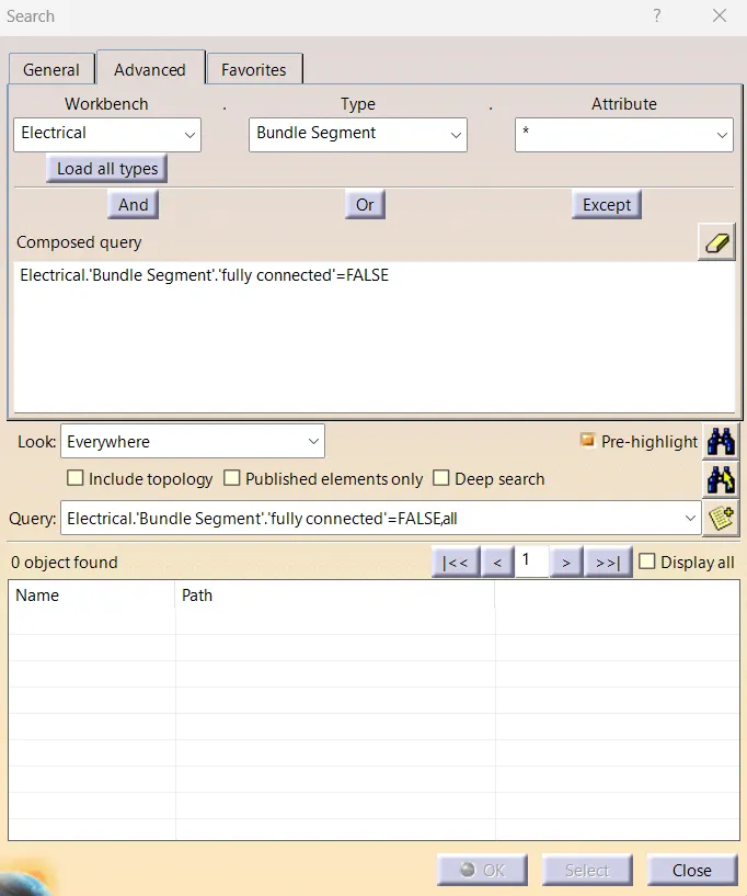
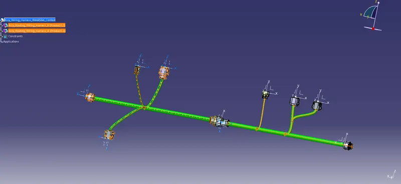
- Go to edit in the above tab and open the search
- Select the Advance tab.
- In the Advance tab, now, select Electrical, Branch bundle, fully connected, and ok.
- select the value as desired - True/False.
- Then click Search / Search and select.
2. Add annotation to all connectors.
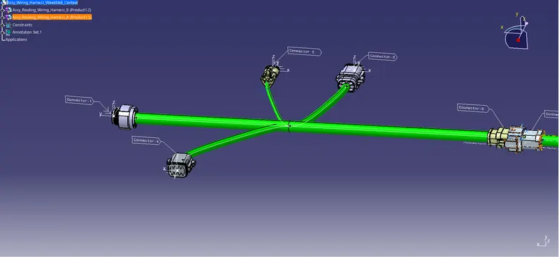
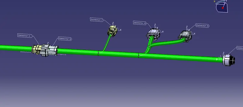
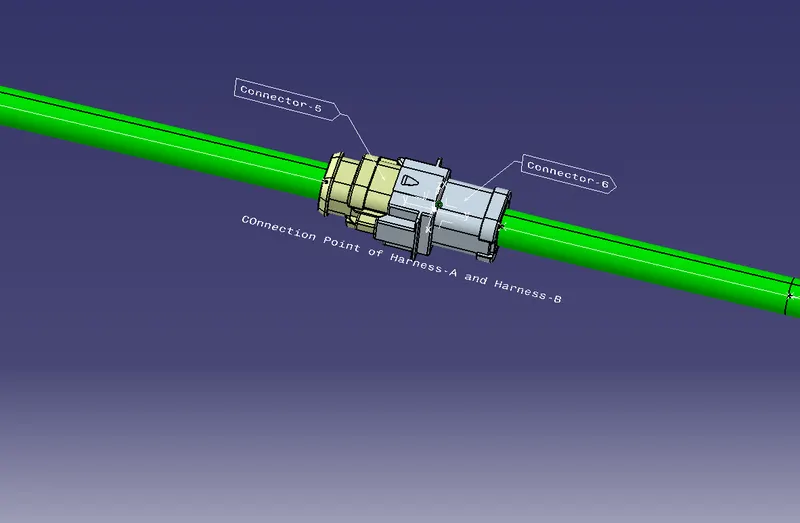
To Annotate the parts, use the options in the Annotate tool bar in the assembly design.
3. Check for the bundle warning.
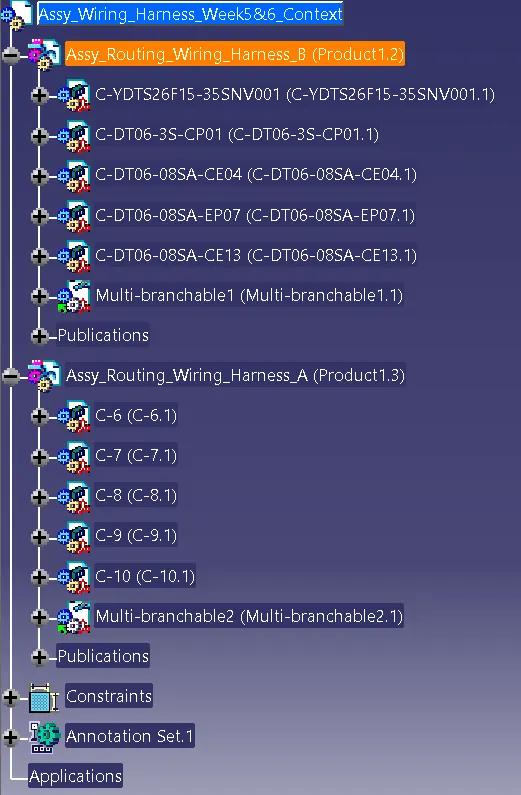
There is no Bundle warning. If there was it is denoted by a yellow marker on the bundle tree.
4. Generate CAT.part of harness assembly and convert it in. igs format.
To convert into .igs format,
- Go to the Tools option in the above toolbar.
- Click on Generate CAT.Part from Product.
- This will convert all the electrical parts into mechanical parts.
- Now save the file as a .igs file in the desired location this can be used to open the file in any other software like Creo, NX, Solidworks, etc.