Wiring harness design in CATIA V5 - 3D modeling Week 5 & 6 Challenge
Steps:
1) Define electrical & geometrical properties for all the connectors(attached).
2) Create harness A & B assembly seperately using Electrical harness assembly.
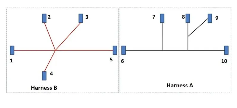
Place the connectors position as per layout required for harness B & A .
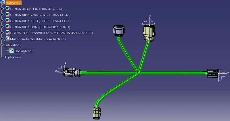
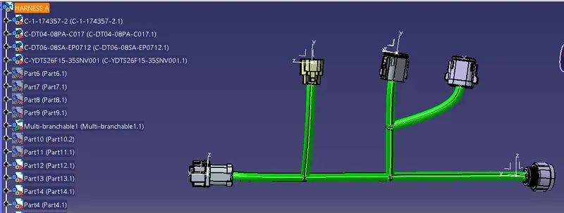
Task 1 :Check Bundle continuity.
Harness B & A
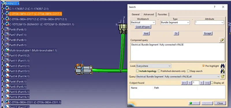
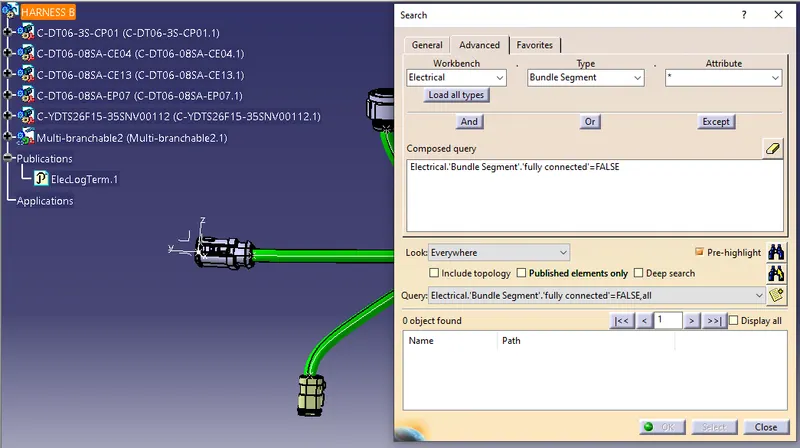
1) Open Harness B & A individually, Go to Edit -> Search->advanced->set
workbench -Electrical
Type->Bundle Segment
Attribute->Fullyconnected->select False->Ok Prehighlight ->Search.
if no bundle is highlighted in window,then all are connected.
Task 2: Adding annotation to connectors
File -> New-> Product-> OK
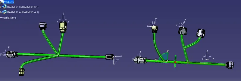
Copy both Harness A & B into Product
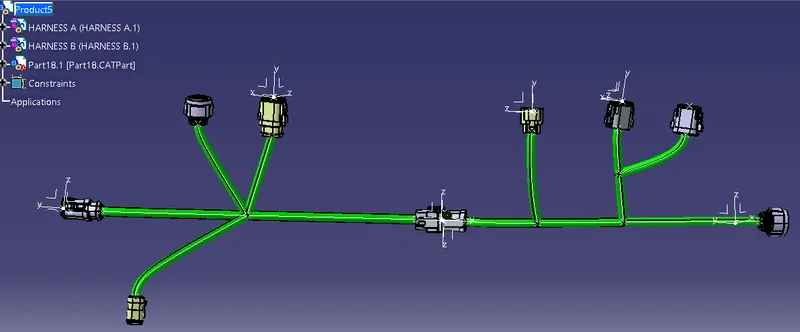
Go to electical harness assembly->Interconnnect both Harness A & B using Connect electrical devices command.
1)Go to assembly design workbench
Activate the product
In Annotation Toolbar click on view creation -> click on connector -> keep type as projection view->OK
click on flag note with ladder click on connector & assume name for each connectors ex:1,2,3 etc.
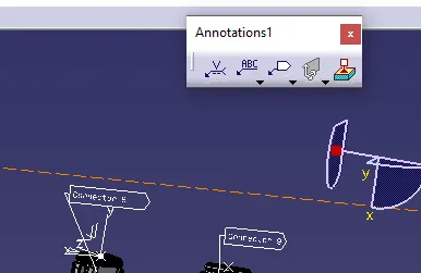
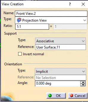
connectors with Annotation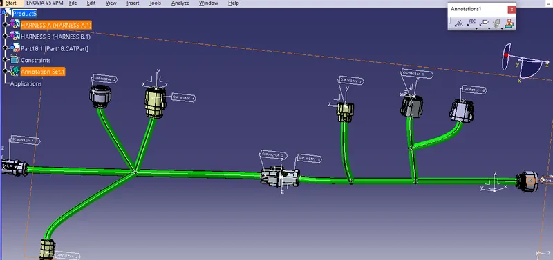
Task 3 : Bundle warning check.
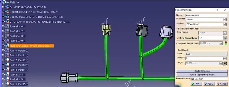
Red highlight on a bundle segment is a sign of warning
Click on red highlighted bundle segment-> computed bend radius should not be less than Bend radius
Error can be resolved by adjusting banching point or changing connector position.
With error:
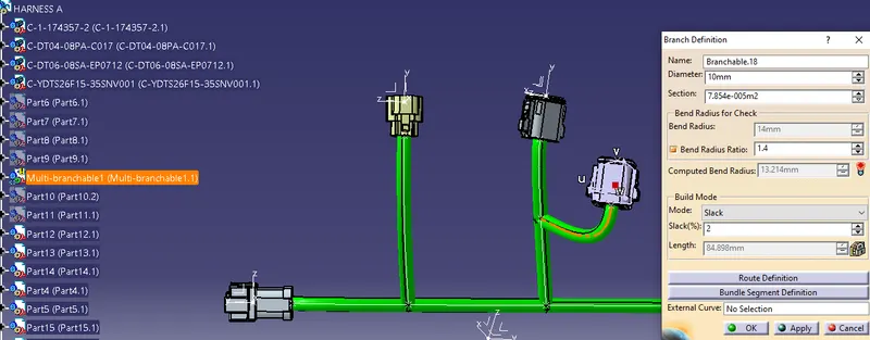
Eroor resolved by adjusting connector position:
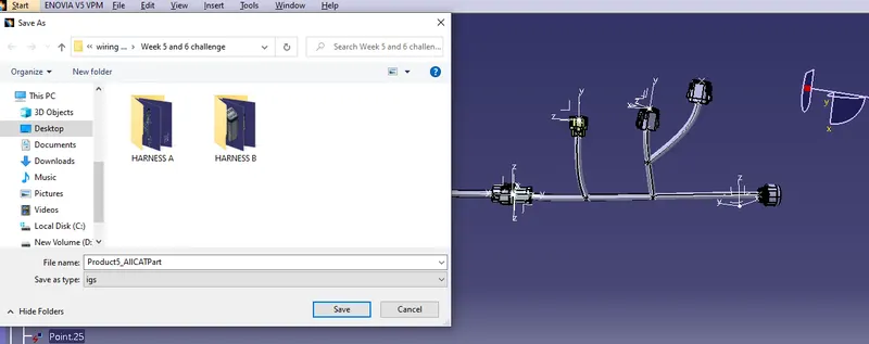
Task 4:Generate CAT.part of harness assembly and convert is in. igs format
Go to Tools -> Generate CAT part from product -> New part number -> click on assembly product or keep new name-> OK
Click on file save Type-> igs-> Save.