Wiring harness design in CATIA V5 - 3D modeling Week 5 & 6 Challenge
Wiring harness design in CATIA V5 - 3D modeling Week 5 & 6 Challenge
Objective:
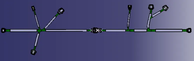
Route the following harness layout in Electrical workbench. Make assumption for harness bundle diameters. Use the connectors provided. After completion of routing:
- Check the bundle Continuity. Add snap of result in submission
- Add annotation to all connectors. Make an assumptions for annotations like connect 1 , 2 etc
- Check for the bundle warning. Add snap.
- Generate CAT.part of harness assembly and convert is in. igs format.
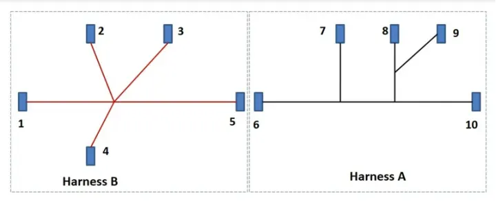
Design Procedure of Harness B:
Creating Reference Sketch:
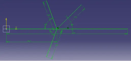

Insert a New Product in Product structure and re-name it Connectors.
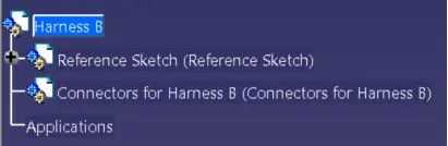
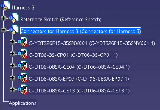
Inserting Connectors from Catalog for Harness B
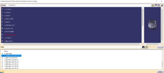
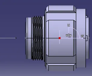
Bring the connectors near to the connecting point as per the input.
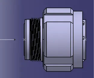
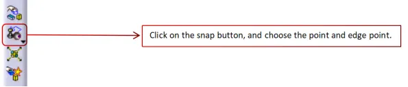
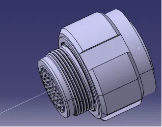
Follow the same procedure for rest of the connectors and align them at the respective points as per input.
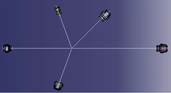
Bundle Creation:

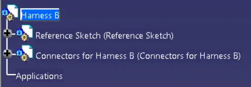
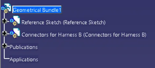
Harness B will be change to Geometric Bundle1 as shown in below image.
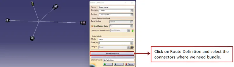
Click on the Branch Definition and start making the bundles between the connectors.
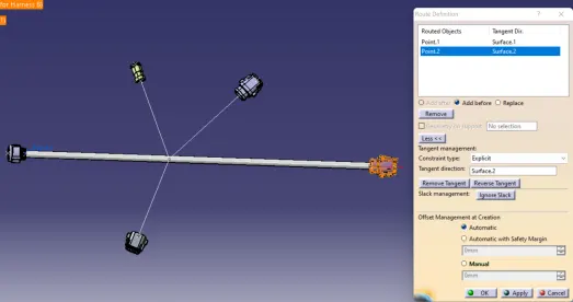
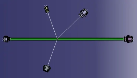
Follow the same procedure to create the bundles for rest of connectors.
Creating Branch Point:
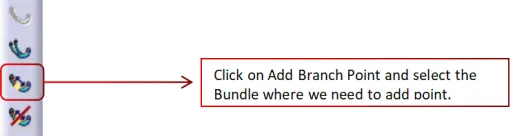
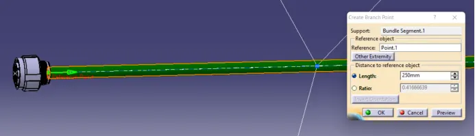
Follow the same procedure to make the branches in the bundles.
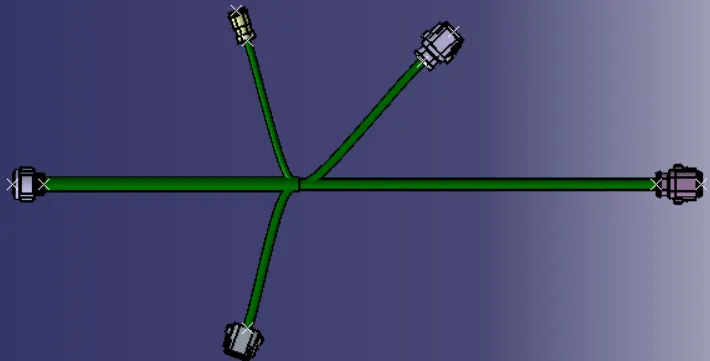
Adding the Protection on the Bundles:
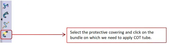
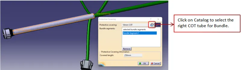
Add relief of 30mm to the COT tube to each side
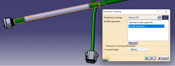
Follow the same steps to cover the each bundles.
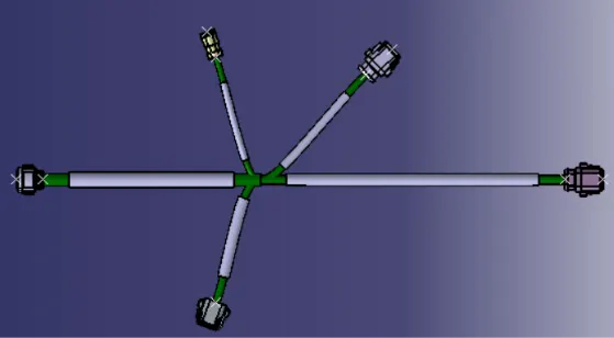
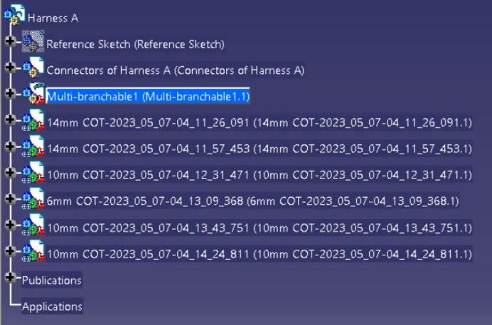
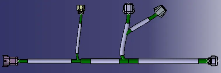
Follow the same procedure for Harness A
Assembly of Harness A and Harness B:
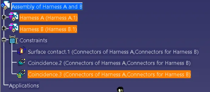
Insert Harness A and Harness B in a New Product(Renamed as Assembly of Harness A and B)
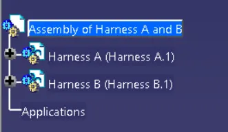

Constraints will be applied between the Harness A and B