Wiring harness design in CATIA V5 - 3D modeling Week 5 & 6 Challenge
Aim :
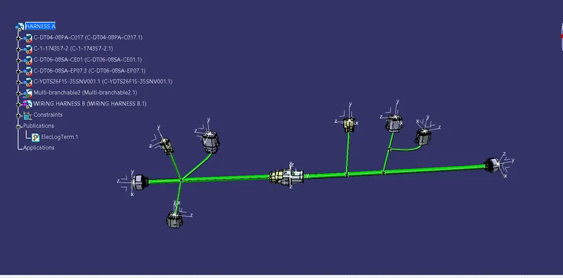
Route the Given harness layout in Electrical workbench & Apply the Conditions.
Ojectives :
- Check the bundle Continuity. Add snap of result in submission
- Add annotation to all connectors. Make an assumptions for annotations like connect 1 , 2 etc
- Check for the bundle warning. Add snap.
- Generate CAT.part of harness assembly and convert is in. igs format.
Procedure :
1st Connector of Harness B :
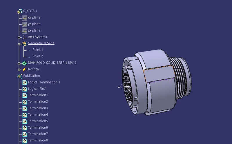
In the Above figure We Have Taken from given source & Merged into Catia V5.
1.Go To the Part design workbench & Taking A middle Point From The Connector Connecting Side As Well As Bundle Connecting Side.
2.Taking the axis Origin of Connector connecting Point.
3.Adusting the y-axis is normal to the face of connector connecting Point & X-axis would be locking side & Z-axis would be Up or down side.
4.Then go to the electrical part design workbench after that defined it as a connector & Add no of terminals it has & defining the connector connection point As well as bundle connection point with respect to their faces & Respresentations.
2nd Connector of Harness B :
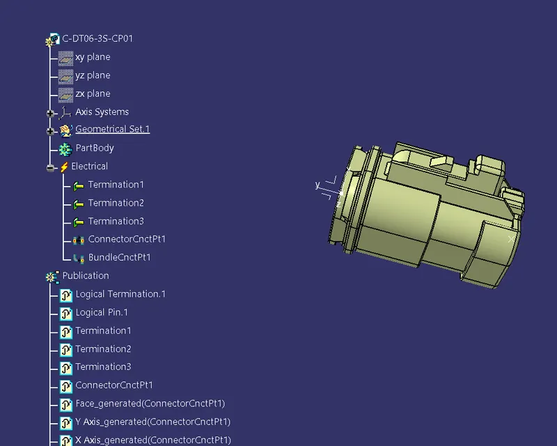
In the Above figure We Have Taken from given source & Merged into Catia V5.
1.Go To the Part design workbench & Taking A middle Point From The Connector Connecting Side As Well As Bundle Connecting Side.
2.Taking the axis Origin of Connector connecting Point.
3.Adusting the y-axis is normal to the face of connector connecting Point & X-axis would be locking side & Z-axis would be Up or down side.
4.Then go to the electrical part design workbench after that defined it as a connector & Add no of terminals it has & defining the connector connection point As well as bundle connection point with respect to their faces & Respresentations
3rd Connector of Harness B :
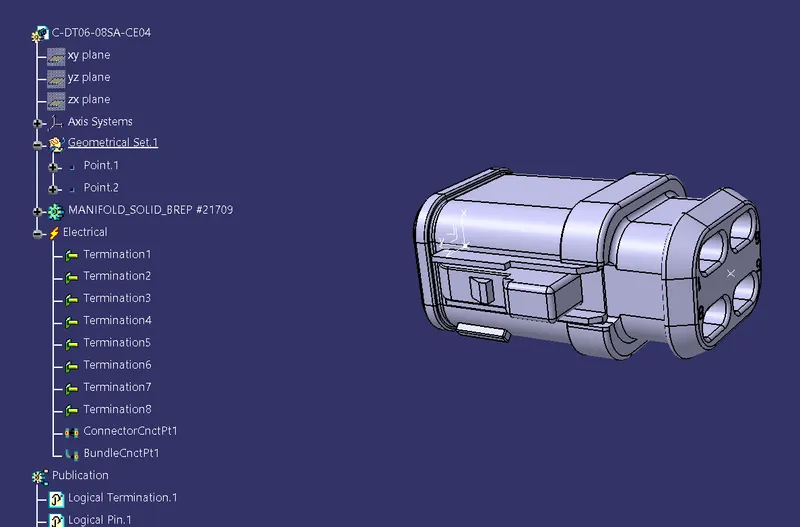
In the Above figure We Have Taken from given source & Merged into Catia V5.
1.Go To the Part design workbench & Taking A middle Point From The Connector Connecting Side As Well As Bundle Connecting Side.
2.Taking the axis Origin of Connector connecting Point.
3.Adusting the y-axis is normal to the face of connector connecting Point & X-axis would be locking side & Z-axis would be Up or down side.
4.Then go to the electrical part design workbench after that defined it as a connector & Add no of terminals it has & defining the connector connection point As well as bundle connection point with respect to their faces & Respresentations
4th Connector of Harness B :
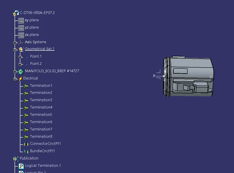
In the Above figure We Have Taken from given source & Merged into Catia V5.
1.Go To the Part design workbench & Taking A middle Point From The Connector Connecting Side As Well As Bundle Connecting Side.
2.Taking the axis Origin of Connector connecting Point.
3.Adusting the y-axis is normal to the face of connector connecting Point & X-axis would be locking side & Z-axis would be Up or down side.
4.Then go to the electrical part design workbench after that defined it as a connector & Add no of terminals it has & defining the connector connection point As well as bundle connection point with respect to their faces & Respresentations
5th Connector of Harness B :
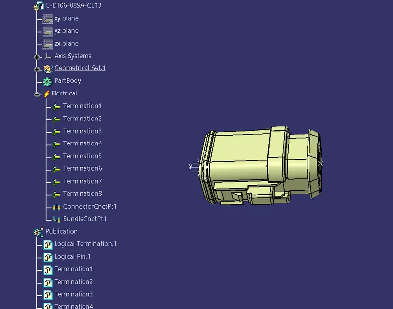
In the Above figure We Have Taken from given source & Merged into Catia V5.
1.Go To the Part design workbench & Taking A middle Point From The Connector Connecting Side As Well As Bundle Connecting Side.
2.Taking the axis Origin of Connector connecting Point.
3.Adusting the y-axis is normal to the face of connector connecting Point & X-axis would be locking side & Z-axis would be Up or down side.
4.Then go to the electrical part design workbench after that defined it as a connector & Add no of terminals it has & defining the connector connection point As well as bundle connection point with respect to their faces & Respresentations
6th Connector of Harness A :
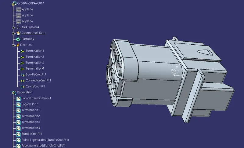
In the Above figure We Have Taken from given source & Merged into Catia V5.
1.Go To the Part design workbench & Taking A middle Point From The Connector Connecting Side As Well As Bundle Connecting Side.
2.Taking the axis Origin of Connector connecting Point.
3.Adusting the y-axis is normal to the face of connector connecting Point & X-axis would be locking side & Z-axis would be Up or down side.
4.Then go to the electrical part design workbench after that defined it as a connector & Add no of terminals it has & defining the connector connection point As well as bundle connection point with respect to their faces & Respresentations.
7th Connector of Harness A :
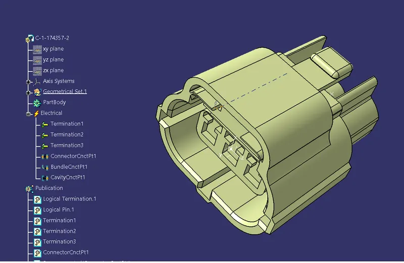
In the Above figure We Have Taken from given source & Merged into Catia V5.
1.Go To the Part design workbench & Taking A middle Point From The Connector Connecting Side As Well As Bundle Connecting Side.
2.Taking the axis Origin of Connector connecting Point.
3.Adusting the y-axis is normal to the face of connector connecting Point & X-axis would be locking side & Z-axis would be Up or down side.
4.Then go to the electrical part design workbench after that defined it as a connector & Add no of terminals it has & defining the connector connection point As well as bundle connection point with respect to their faces & Respresentations.
8th Connector of Harness A :
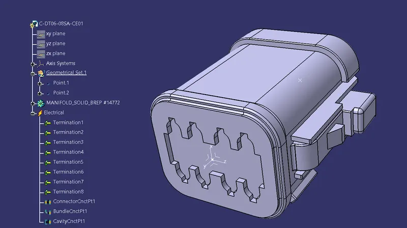
In the Above figure We Have Taken from given source & Merged into Catia V5.
1.Go To the Part design workbench & Taking A middle Point From The Connector Connecting Side As Well As Bundle Connecting Side.
2.Taking the axis Origin of Connector connecting Point.
3.Adusting the y-axis is normal to the face of connector connecting Point & X-axis would be locking side & Z-axis would be Up or down side.
4.Then go to the electrical part design workbench after that defined it as a connector & Add no of terminals it has & defining the connector connection point As well as bundle connection point with respect to their faces & Respresentations.
9th Connector of Harness A :
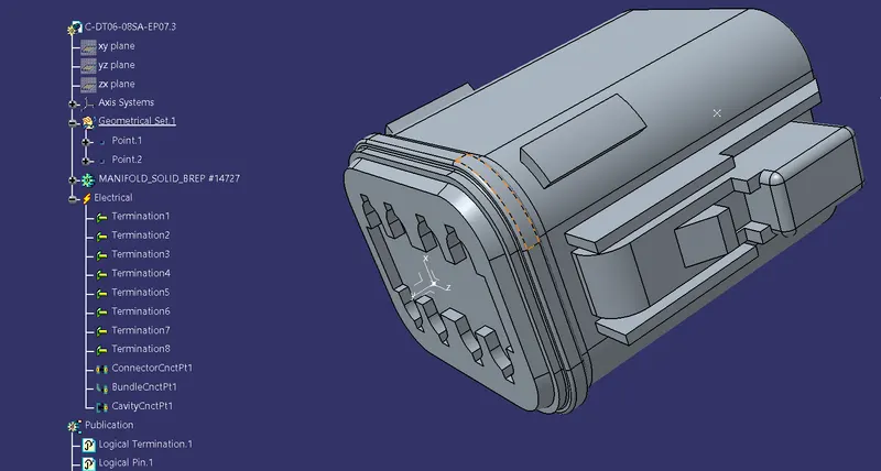
In the Above figure We Have Taken from given source & Merged into Catia V5.
1.Go To the Part design workbench & Taking A middle Point From The Connector Connecting Side As Well As Bundle Connecting Side.
2.Taking the axis Origin of Connector connecting Point.
3.Adusting the y-axis is normal to the face of connector connecting Point & X-axis would be locking side & Z-axis would be Up or down side.
4.Then go to the electrical part design workbench after that defined it as a connector & Add no of terminals it has & defining the connector connection point As well as bundle connection point with respect to their faces & Respresentations.
10th Connector of Harness A :
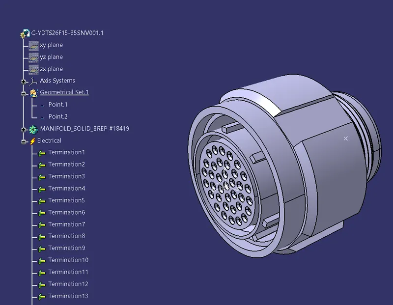
In the Above figure We Have Taken from given source & Merged into Catia V5.
1.Go To the Part design workbench & Taking A middle Point From The Connector Connecting Side As Well As Bundle Connecting Side.
2.Taking the axis Origin of Connector connecting Point.
3.Adusting the y-axis is normal to the face of connector connecting Point & X-axis would be locking side & Z-axis would be Up or down side.
4.Then go to the electrical part design workbench after that defined it as a connector & Add no of terminals it has & defining the connector connection point As well as bundle connection point with respect to their faces & Respresentations.
Electrical harness Assembly B:
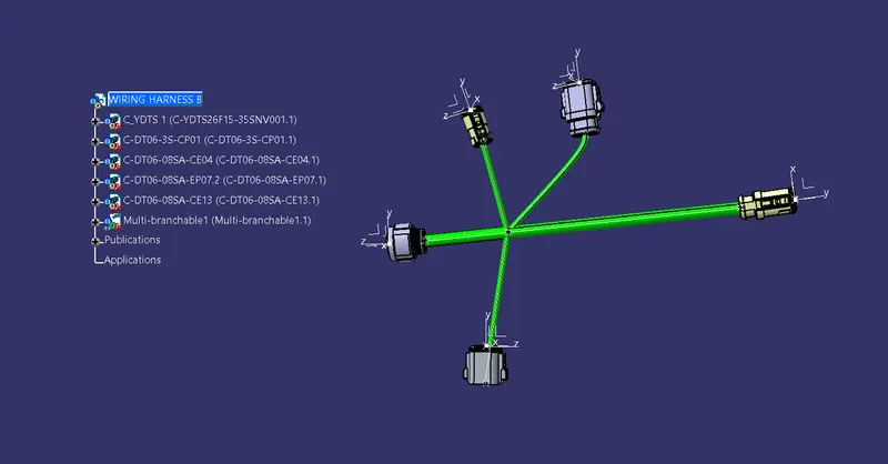
Then Go to the electrical harness Assembly Define the product as an geometric bundle.
Then go the multibranchable point Route the bundles And suiatable break points with respect to the given Diagram.
Electrical harness Assembly A:
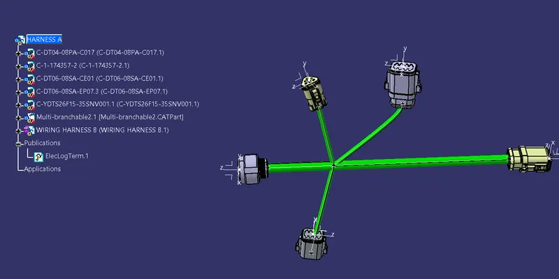
Then Go to the electrical harness Assembly Define the product as an geometric bundle.
Then go the multibranchable point Route the bundles And suiatable break points with respect to the given Diagram.
Connecting Electrically :