Wiring harness design in CATIA V5 - 3D modeling Week 5 & 6 Challenge
AIM: The aim of this project is to,
- Check the bundle Continuity.
- Add annotation to all connectors.
- Check for the bundle warning. Add snap
CHECKING BUNDLE CONNECTIVITY:
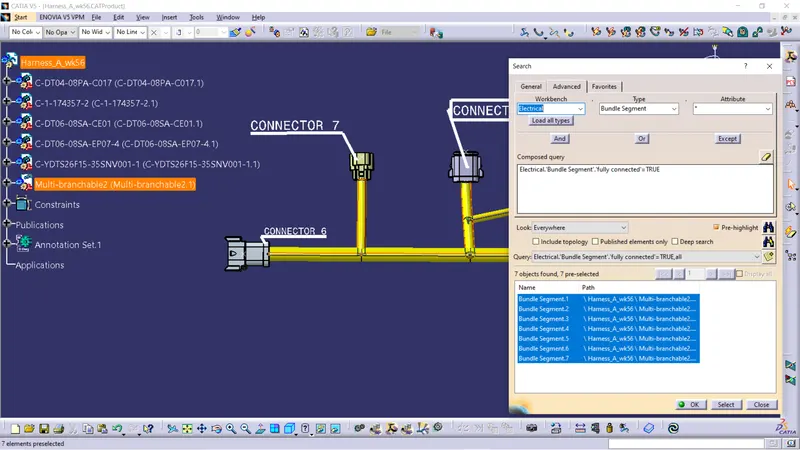
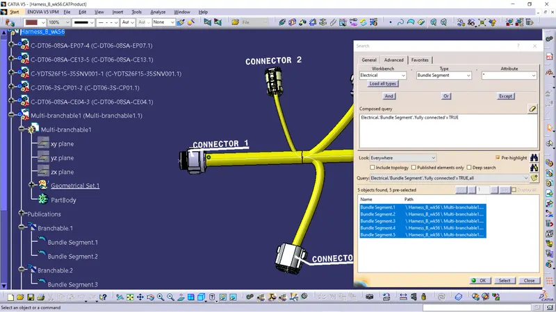
To check bundle connectivity go for edit-------Search----- Select electrical workbench-------Select bundle segment and then select for fully connected also check whether connection query should be false or true.
Harness A bundle connecticity is checked and it is fully connected.
Harness B bundle connecticity is checked and it is fully connected.
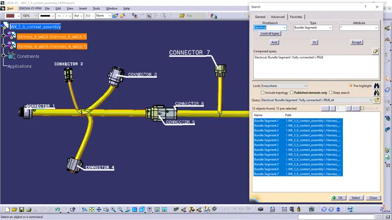
After interconnecting the bundle is checked for connectivity,
2.Each and every connectors are annotated accordingly,
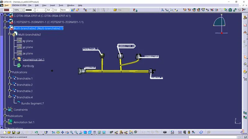
For annotations we have to select the plane for text and choose the type of headings for annotating.
Harness A annotations,
Whole assembly is annotated as shown below,
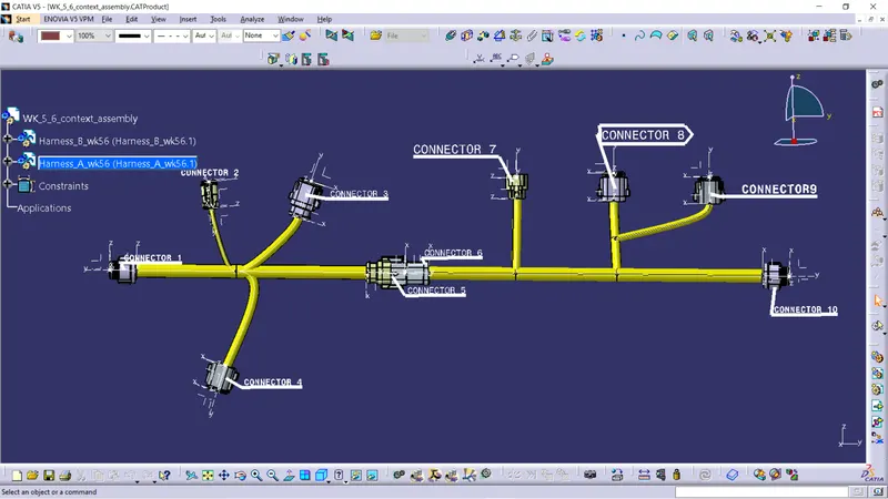
Bundle Warning : If the bend radius of the bundle is more than the computed one it will show a red error in the axis of bundle. We have to check for tangency, reduction of bend radius, branch point adjustment , Vector alignment for resolving this issue.
Generating CAT part:
For generating CAT part from product go to tools---- select generate CAT part from product and then select the assembly ,it will automatically show the part number and click OK. after generating CAT part it shows the save as window there you can select the required type.
After converting the assembly components will be converted to part bodies as shown below,
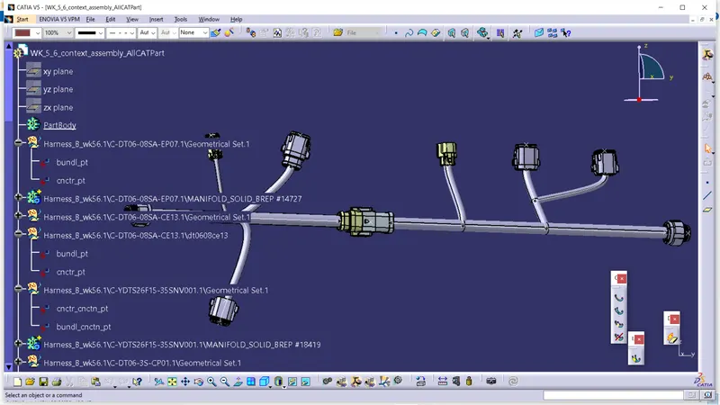
CONCLUSION:
The bundle connection is checked for continuity and the snap is provided.
Required annotations are provided to the connectors.
The generated catpart is converted to igs and attached below.