Wiring harness design in CATIA V5 - 3D modeling Week 5 & 6 Challenge
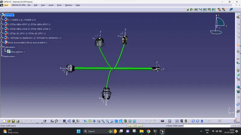
Harness B:
- In Harness B, iused the connectors in the given discription.
- then i give the connector point and bundle entry for each connectors.
- after that i started routing definition for routing the bundle entry.
- then we have to add the branch point at the middle of the 1&2 connectors.
- then i give the routing definition for 2nd connector.
- now we have to create branch point at the 2nd connector. after that i give the routing definition for 3rd connector.
- then i create another bundle entry using branch point for 4th connector.
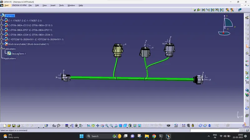
Harness A:
- In Harness A, i used the same process for connecting the connector in the given discription.
- then i gave the connector point and bundle entry for each connectors.
- after that i started routing definition for routing the bundle entry.
- then we have to add the branch point at the middle of the 6&10 connectors.
- then i give the routing definition for 7th connector.
- now we have to create branch point at the 8th connector.
- after that i create another routing definition for 9th connector.
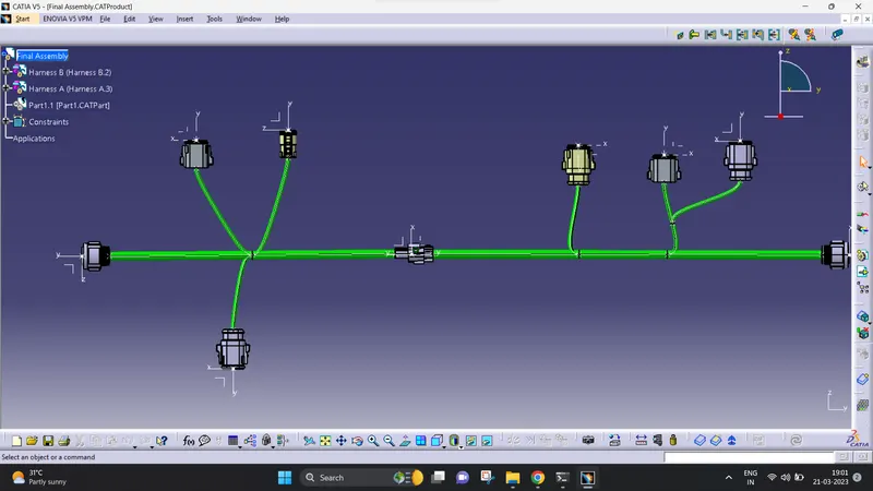
Now i'm going to connect the both Haress A & Haness B and what are procedure for connecting them:
- i'm going to create the new product file connecting them.
- after that i open the both Harness A&B file.
- then I copy and paste it into new Product file it named as (final assembly).
- now i used the snap tool for joining the both connector using axis point.
- finally i used the connect electrical device to constraint the both connectors.
That's all i give the above steps are connect the connectors and i attach the images in below.