Wiring harness design in CATIA V5 - 3D modeling Week 5 & 6 Challenge
Q1. Route the following harness layout in Electrical workbench. Make assumption for harness bundle diameters. Use the connectors provided. After completion of routing,
- Check the bundle Continuity. Add snap of result in submission
- Add annotation to all connectors. Make an assumptions for annotations like connect 1 , 2 etc
- Check for the bundle warning. Add snap.
- Generate CAT.part of harness assembly and convert is in. igs format.
The Electrical connectors are denoted by numbers in the above figure
- There are ten separate locations with various connector kinds.
- The two generated harnesses'bundle continuity must be examined.
- After the two harnesses have been made, they must now be eletrically connected.
- Check for bundle warnings on harness A and B.
- Mark each connector in harness A and harness B with a note.
- The conversion of the final harness file into the IGS file format is the project's ultimate objective.
STEP:- 1
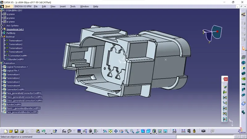
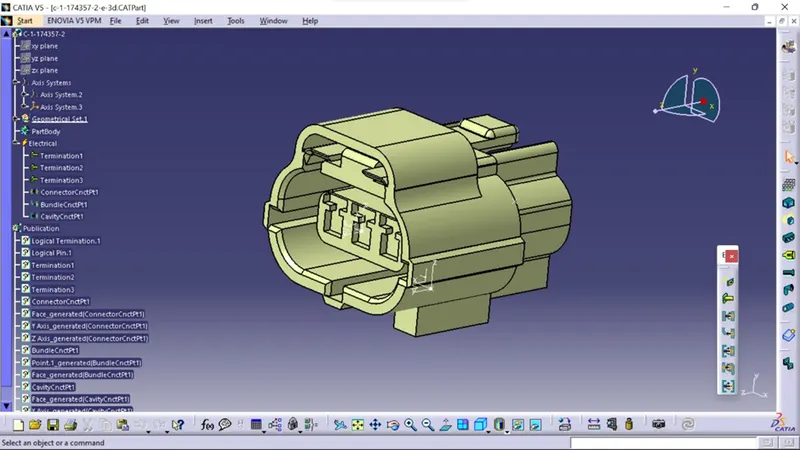
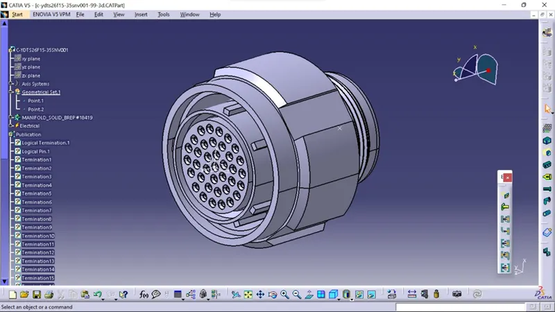
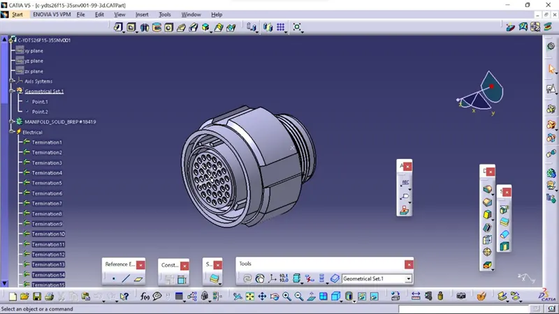
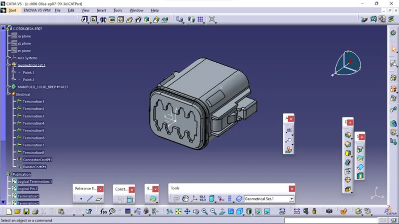
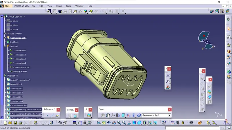
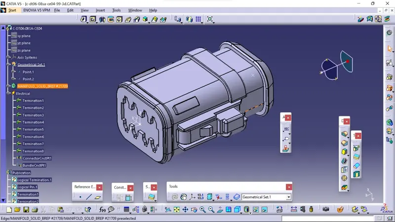
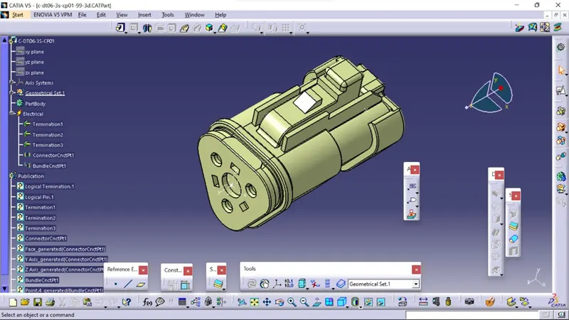
For all the electrical connectors that will be used in the wire harness, create geometric and electrical definitions.
Connector use in Harness A
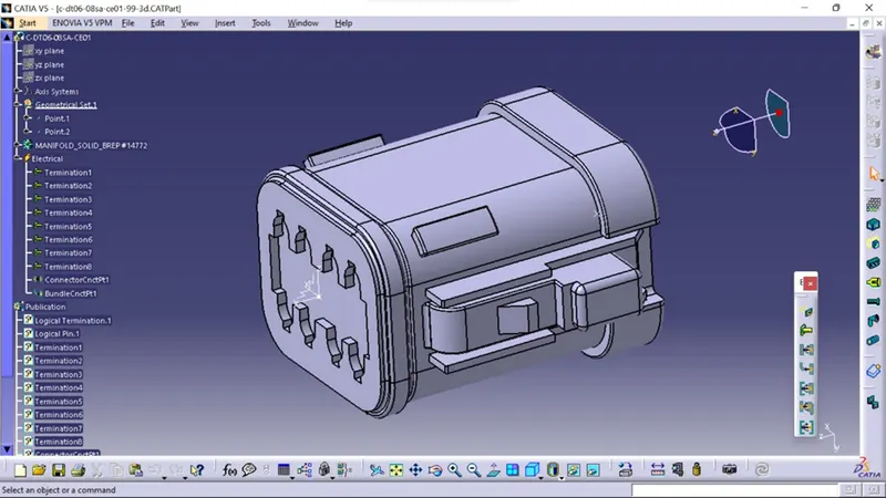
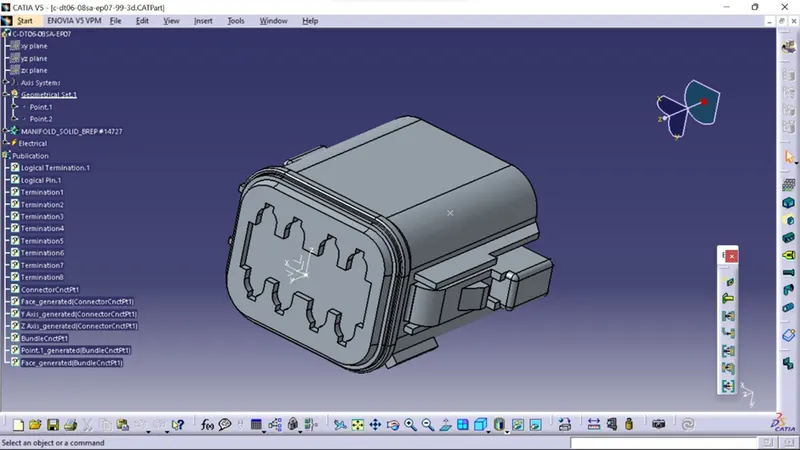
Connector use in Harness B
STEP:-2
Create harness A and B as illustrated below using the CATIA V5 electrical harness workbench
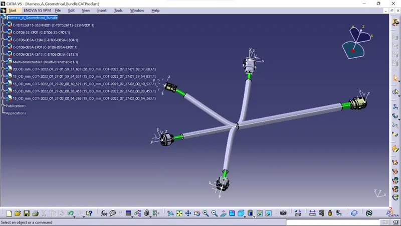
First, all of th connectors are positioned correctly. Second, between the connectors, bundle segments containing branch points and branches are generated, as illustrated below.
For different bundle segments, bundle diameters of 15mm,12mm,8mm, and 5mm are presumptive. The bend ratio is 1.4 and the slack is 0% for the entire bundle.
Harness A
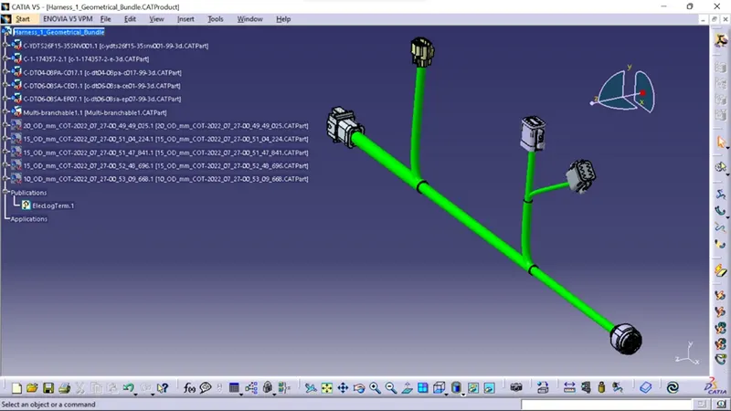
End are kept 30mm away from connector by safty courrugate tubes.
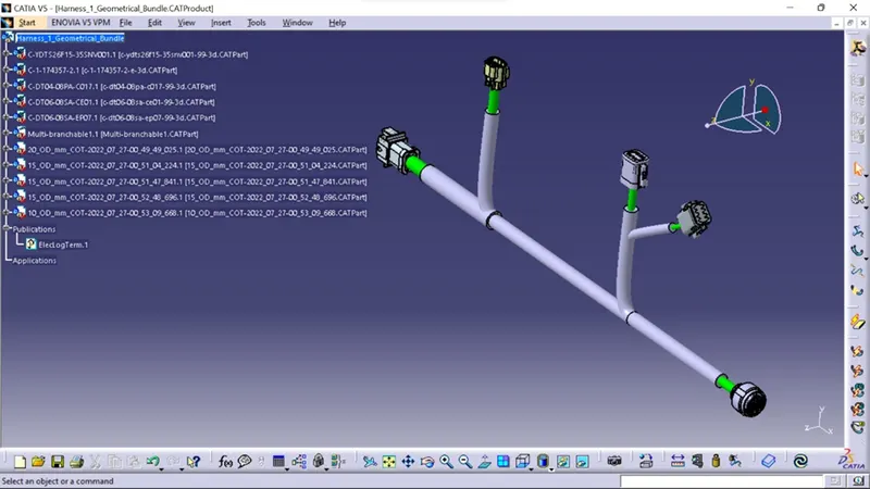
Harness B
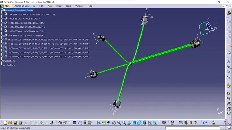
End are kept 30mm away from connector by safty corrugated tubes.
STEP:-3
The bundle continuity needs to be examined after harness A and harness B are created.
Then, go to Edit>Search>Advanced>Electrical Workbench>Type-Bundle Segment>Attribute-Fully Connected. Make sure multi-branchable is chosen.
If "TRUE" is chosen, all bundle segments that are connected will be shown;if "FALSE," all bundle segments that are not connected will be shown.
STEP:-4
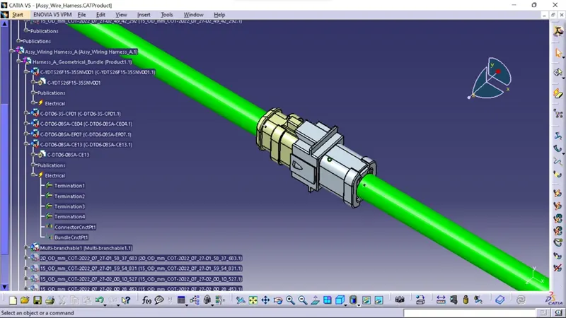
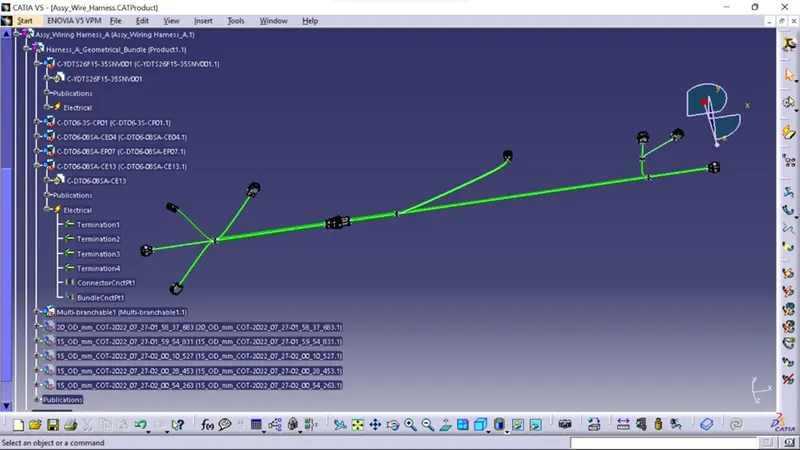
Wiring Harness A and Harness B must be electrically connected in this step. The two harnesses need to be electrically connected, which requires a few procedures.
Create a new product file in CATIA and rename it to "Assy Wire Harness" to get things started.
The final harness assembly can then be built by adding harness A and harness B to the newly formed product file. Connect the male and female connectors inside the electrical assembly design workbench as illustrated below.
STEP:-5
We'll check Harness A and B in this phase to see if there are any bundle alerts.
Geometric bundle alerts for the Bend radius, Bundle diameter, and vector position are shown. A yellow flash will appear in the tree structure adjacent to the problematic branchable if these input or values are wrong. We can solve the issue by introducing slack or by modifying the vector position of the segment point, depending on the path taken by the bundle segment. There isn't an error in this instance.
STEP:-6
We will label each electrical connector in this phase.
Annotations are used to show extra information as well as connecting functionalities. They are described in the Assembly Design Workbench of CATIA V5.
Prior to placing the annotation, we must choose a plane.
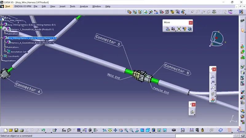
Then, choose the "flag note with ladder" option, and then click each connector separately. Provide each connector the information they require, as illustrated below.
we should enlarge the font size of the notes to make them more noticeable after adding annotations to all of the connectors.
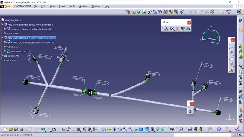
STEP:-7
Our Final Harness Assembly file needs to be converted into IGS format before we can move on. The steps listed below must be followed in order to achieve this.
Mechanical Assembly Workbench>Tools>Catalog part generation from product
The complete product file is turned into a single part when the CAT part has been created. It is now evident that the bundle segments are all grey in hue. To match the Final Harness Assembly, we'll go back and add green colour to each bundle segment.
Lastly, we may utilise the "SAVE AS" function to save the CAT component file as an IGS file, as demonstrated below.
here are the solution of above question .
ALL the important file and image are attached with Answer body