Wiring harness design in CATIA V5 - 3D modeling Week 5 & 6 Challenge
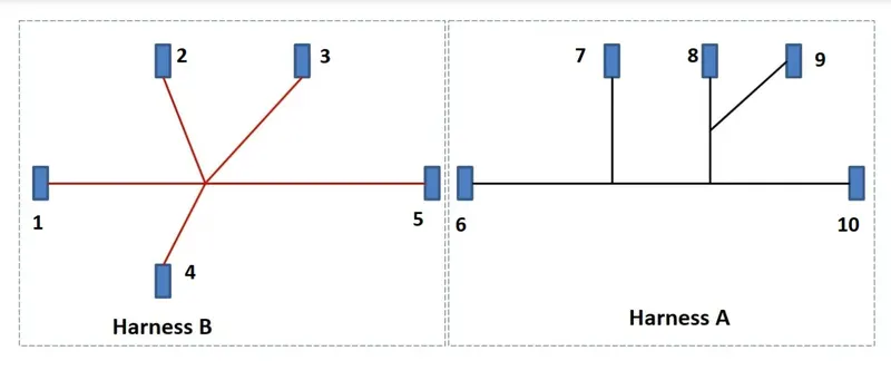
Route the following harness layout in the Electrical workbench. Make assumptions for harness bundle diameters. Use the connectors provided. After completion of routing,
Harness A
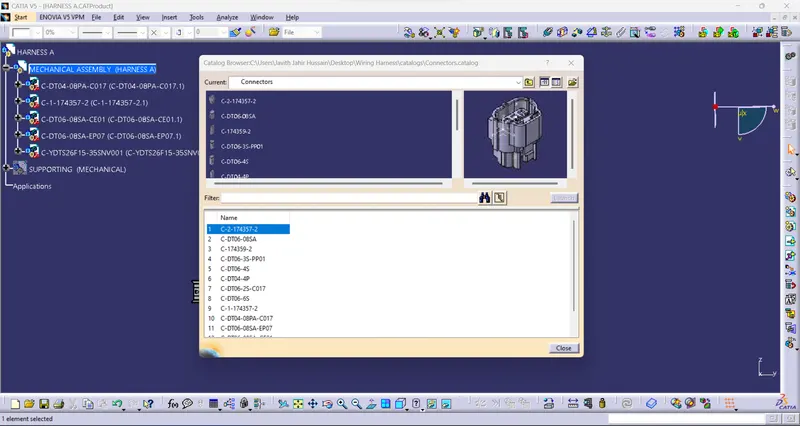
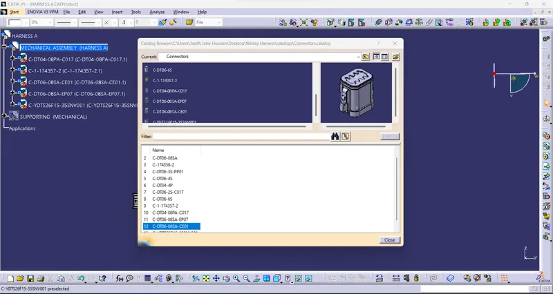
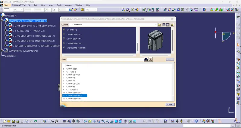
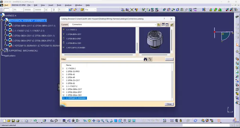
Catalog:
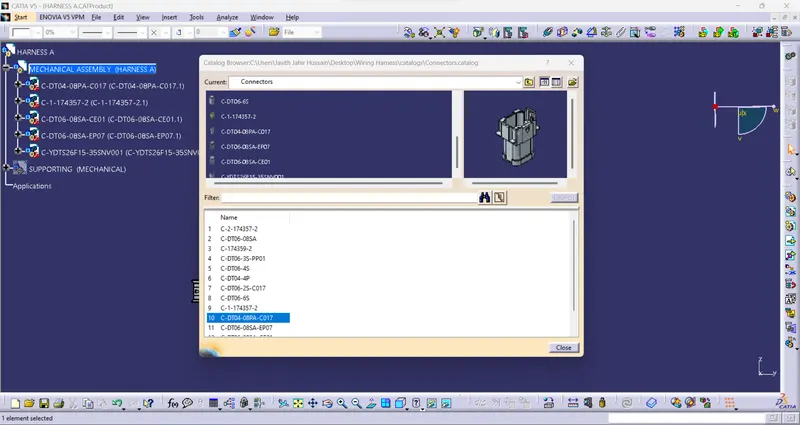
- Adding all connectors into the catalog.
- Then add the required connector to the "Electrical assembly workbench".
- Arrange the connector given the "Harness A" layout.
Geomentrycal bundle:
- Arranging the connector as per the "Harness A" layout.
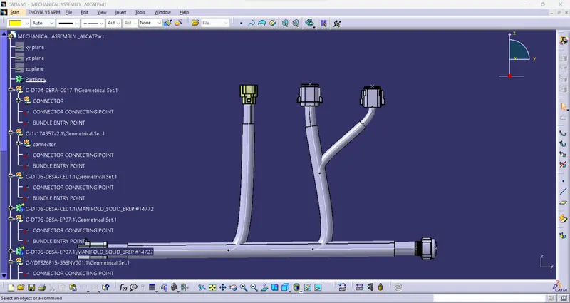
- Then create the bundle using the "Electrical harness assembly workbench".
- First, generate the "GEOMETRICAL BUNDLE".
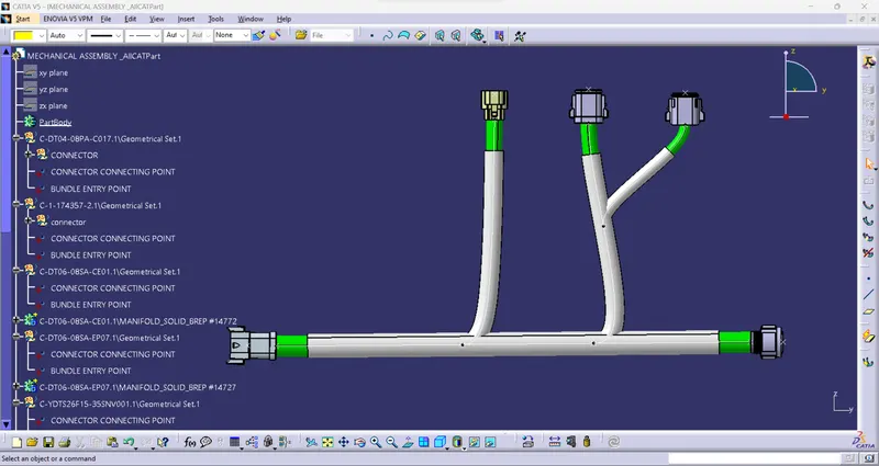
- Then Add the bundle between the connector to the connector.
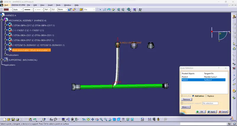
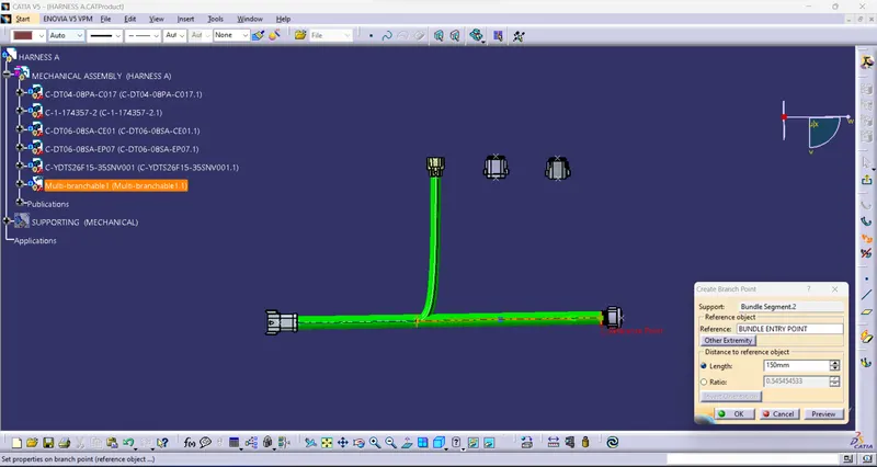
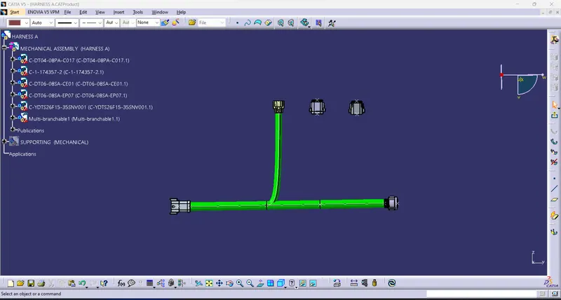
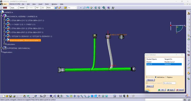
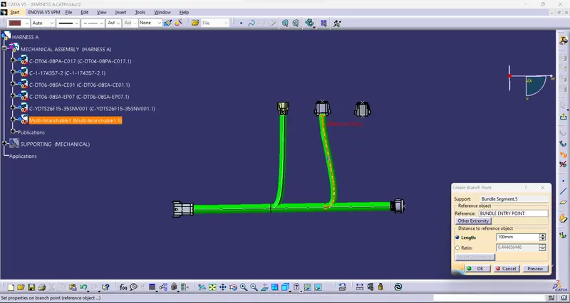
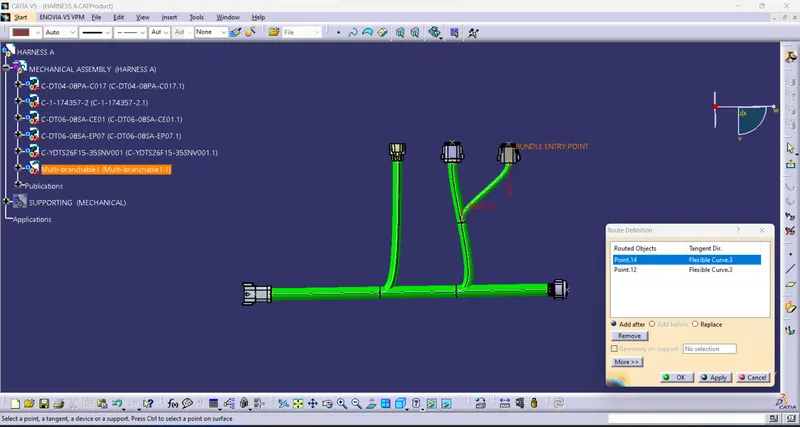
- Add the Branch point using the "Add branch" command.
- Branch point adding to use to connect connector.
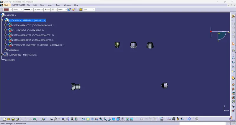
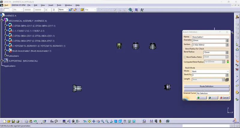
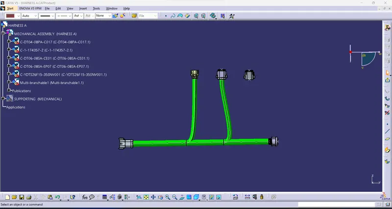
Multi-branch:
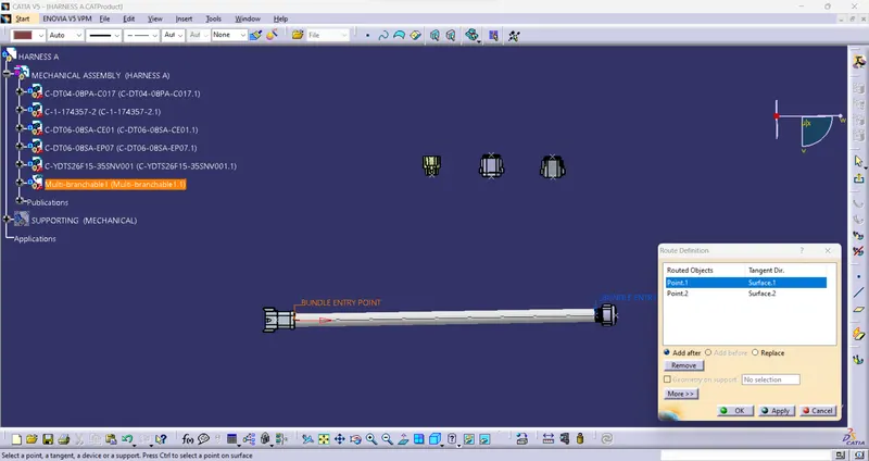
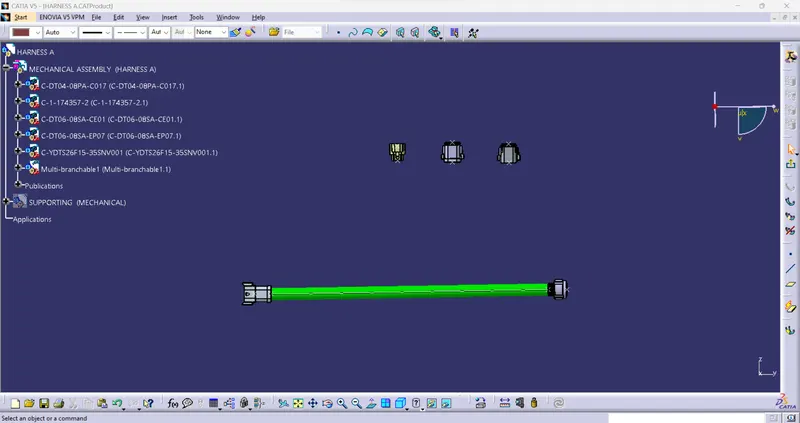
Add branch point:
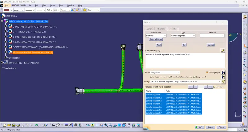
Check the bundle Continuity:
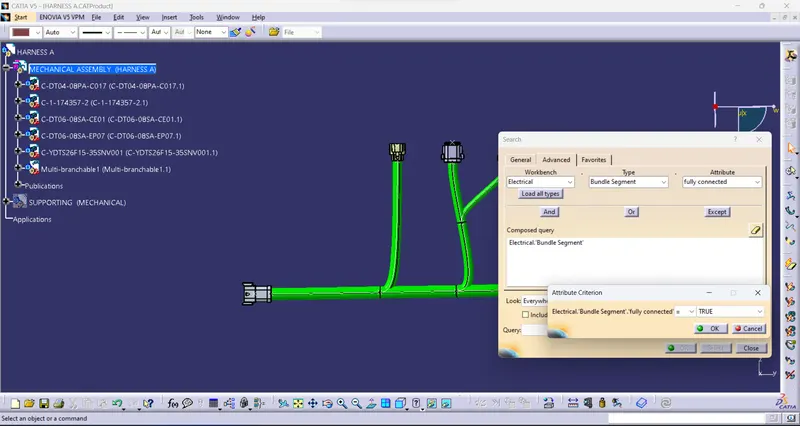
- Completely connected to all connectors and bundles.
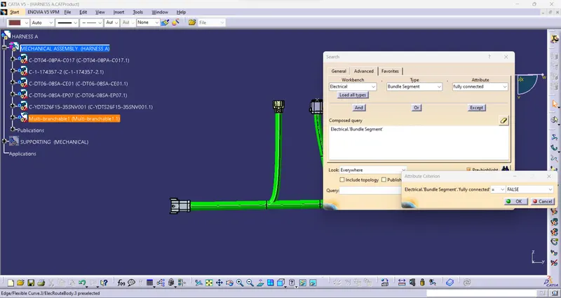
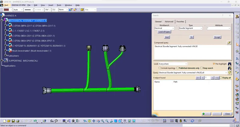
- Check the connector and bundle are completely connected or not.
- Using the command "FULLY CONNECTED"
- TRUE= Fully connected bundles.
- FALSE=Not connected bundles.
- Show the result.
ADD PROTECTION:
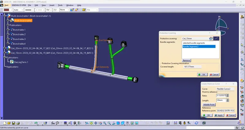
- Providing Corrugated tubes for protection for the bundles.
- Providing various size tubes.
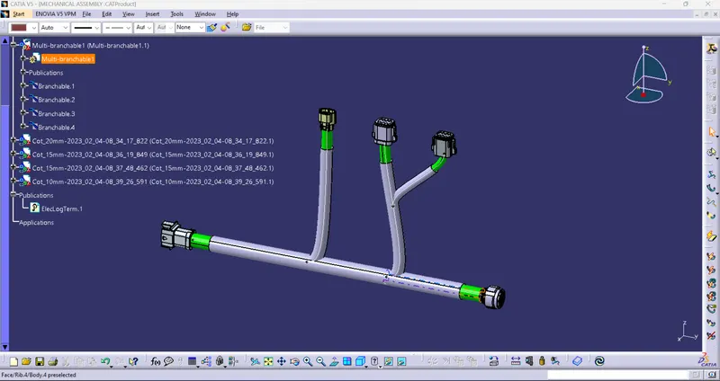
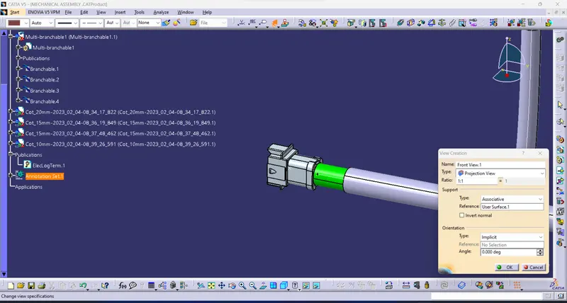
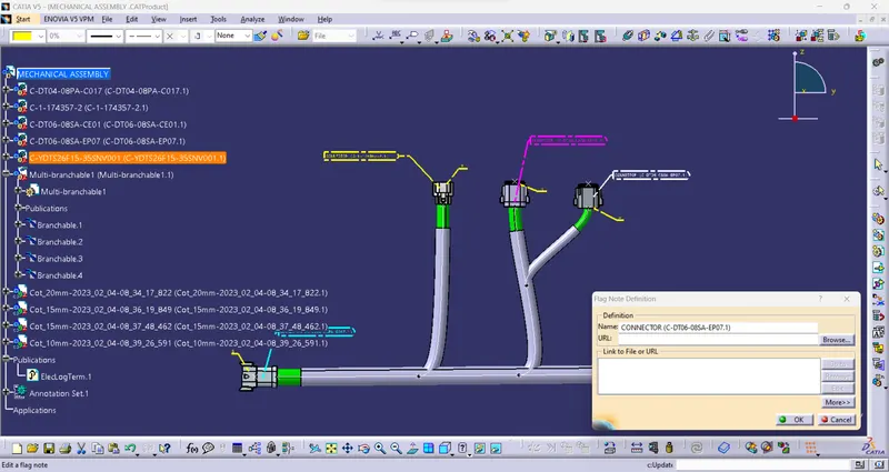
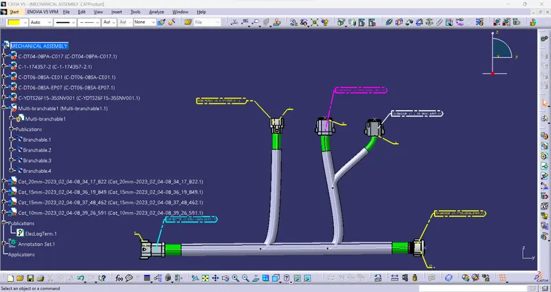
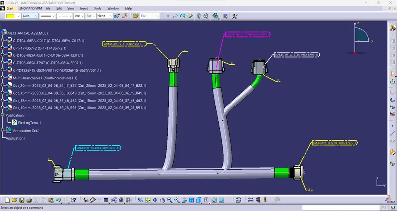
3D ANNOTATION:
- The 3D annotation is used on the wiring harness to show the connector function and additional notes.
- This annotation is to be added to the harness data to show specific information relating to the harness (wire type, wire spec, any additional information, and comments).
BUNDLE WARNING:
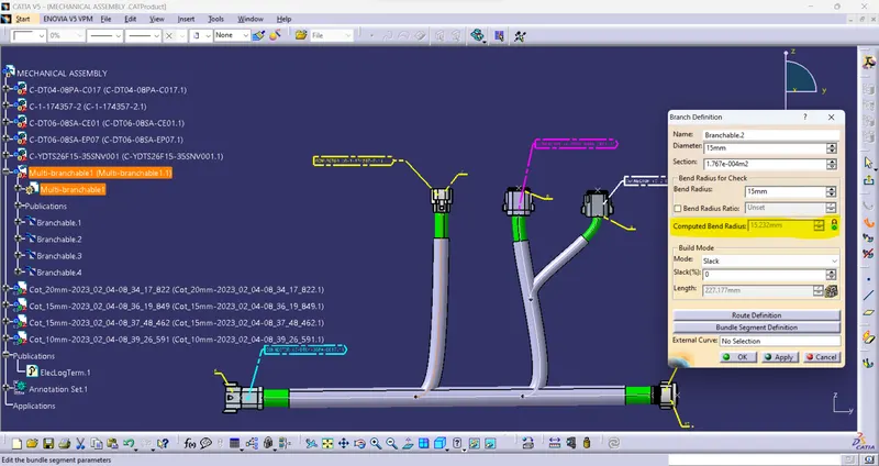
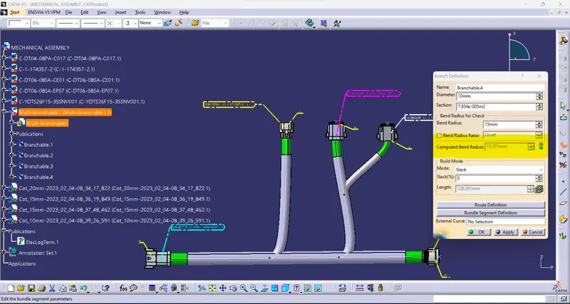
- These warnings are usually displayed in the structure of the wire harness geometrical bundle.
- it's usually related to the bend radius, bundle diameter, or the vector position of your bundle segments.
- If any issues are found the yellow flash warning symbol will appear in the tree structure of the geometrical bundle.
- Resolve the problem using the following:
- Change the supporting clips' location/ direction.
- Update new vector points.
- Add to slack to solve the problem for some time.
- Update branch point direction.
- Provide a new supported curve using Tangent management and From curve.
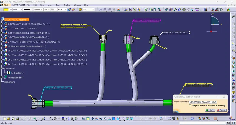
Generate CAT.part of harness assembly and convert is in. igs format
- It is sometimes used to be represented by some other tools (NX-CAD, CREO, etc.,)or lower vision Catia software.
- Create the CAT.part and convert the IGES or STEP file for the given requirements.
HARNESS B
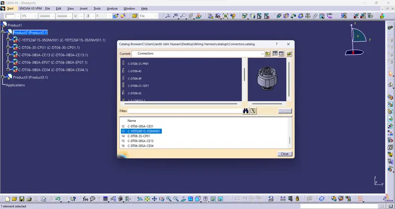
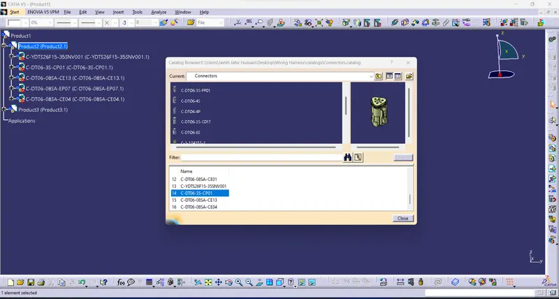
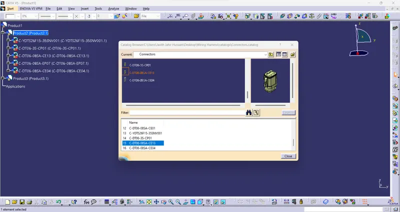
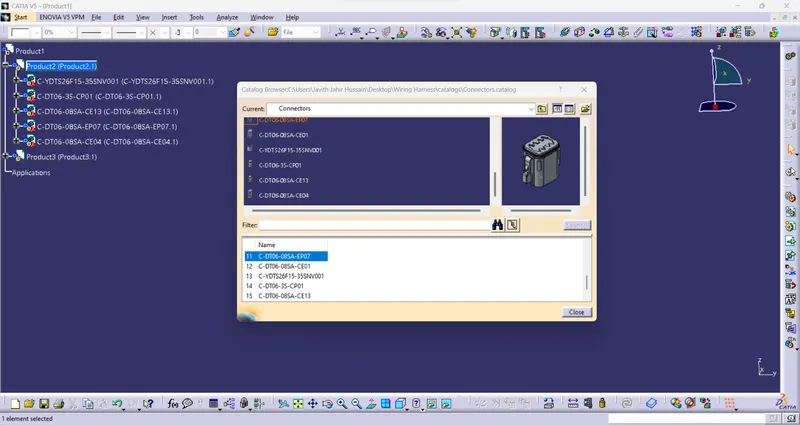
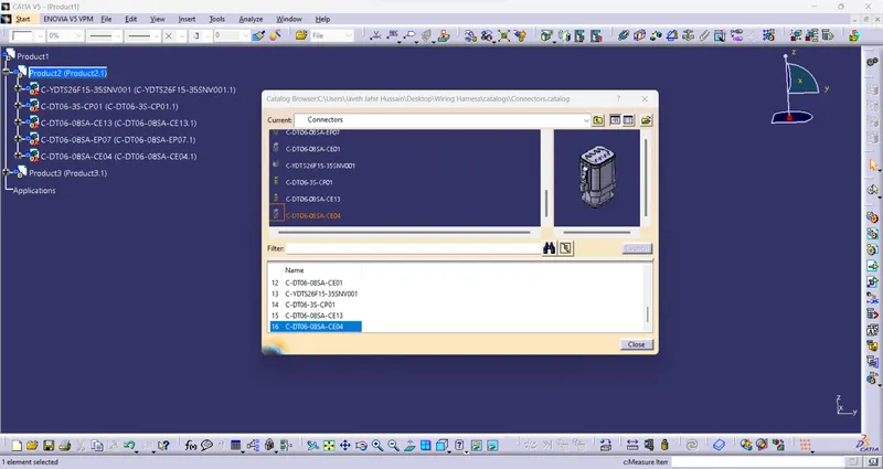
Catalog:
- Adding all connectors into the catalog.
- Then add the required connector to the "Electrical assembly workbench".
- Arrange the connector given the "Harness B" layout.
Geomentrycal bundle:
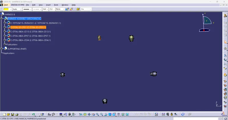
- Arranging the connector as per the "Harness A" layout.
- Then create the bundle using the "Electrical harness assembly workbench".
- First, generate the "GEOMETRICAL BUNDLE".
- Then Add the bundle between the connector to the connector.
- Add the Branch point using the "Add branch" command.
- Branch point adding to use to connect connector.
Multi-branch:
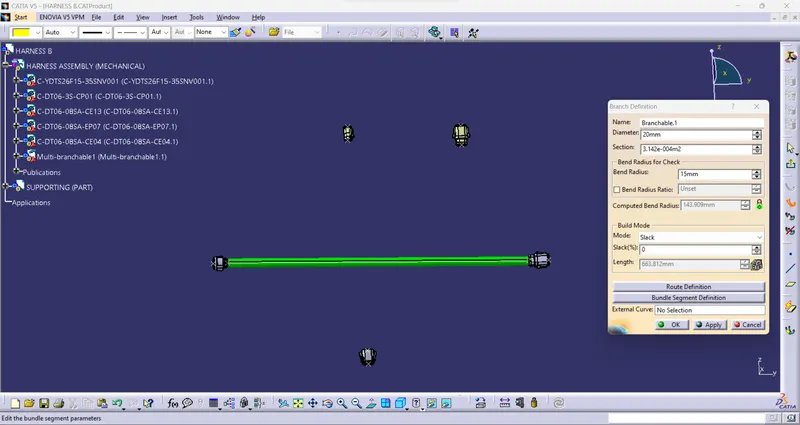
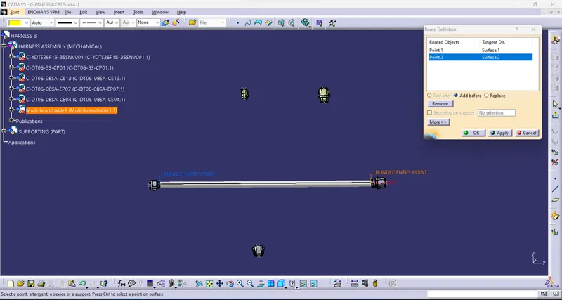
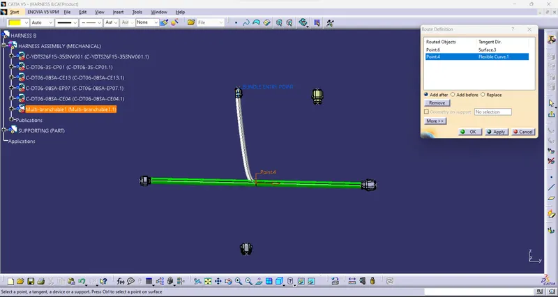
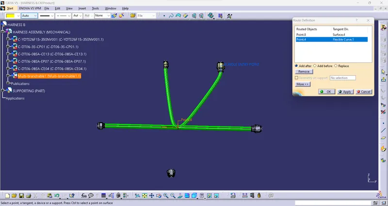
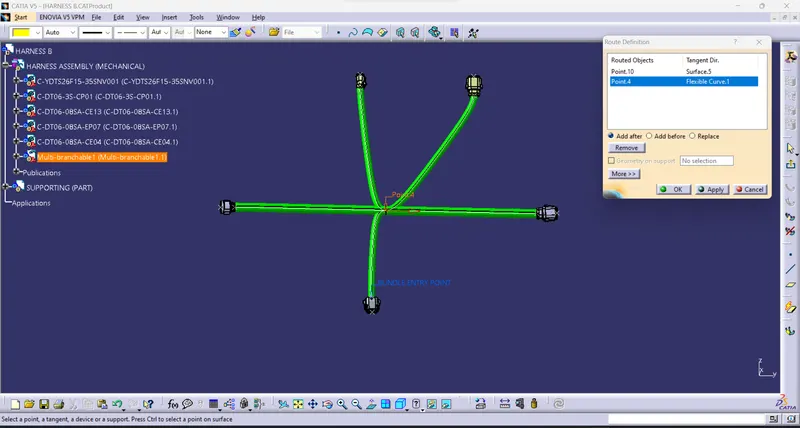
Add branch point:
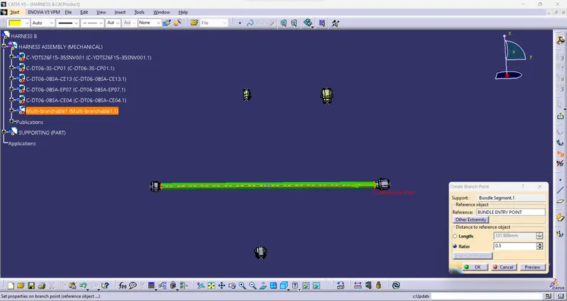
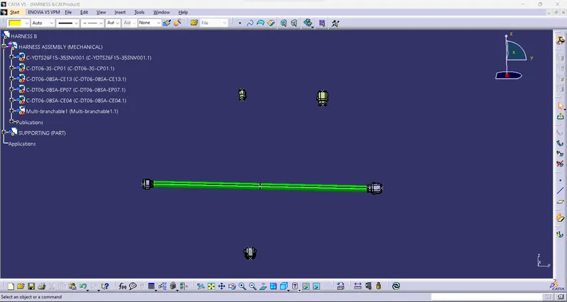
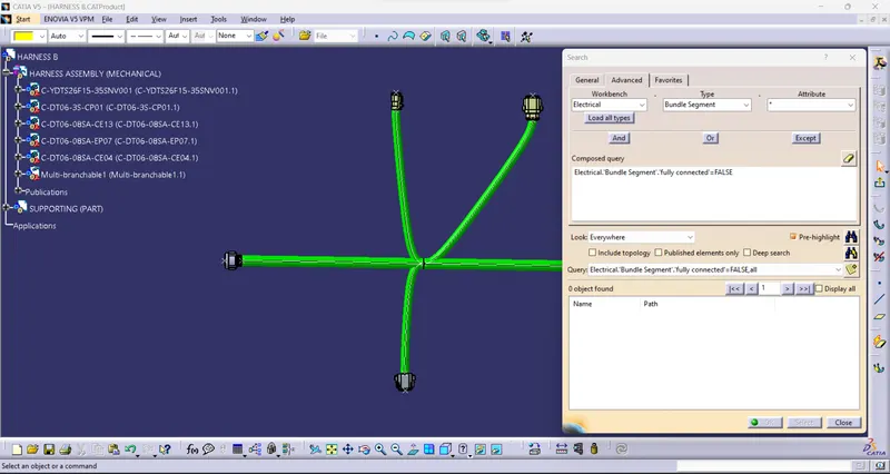
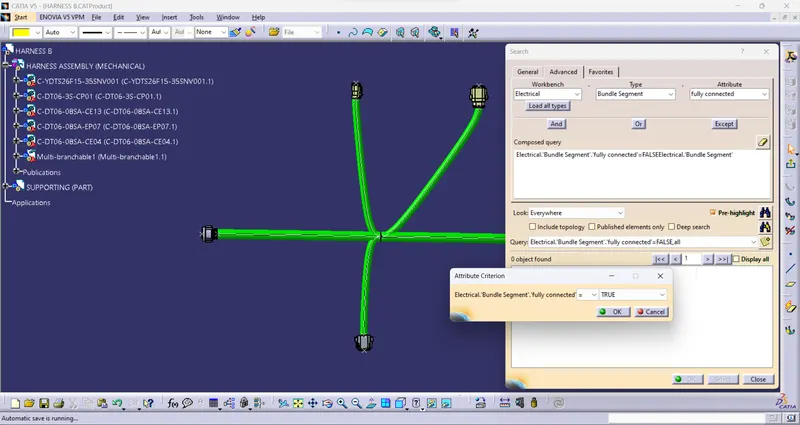
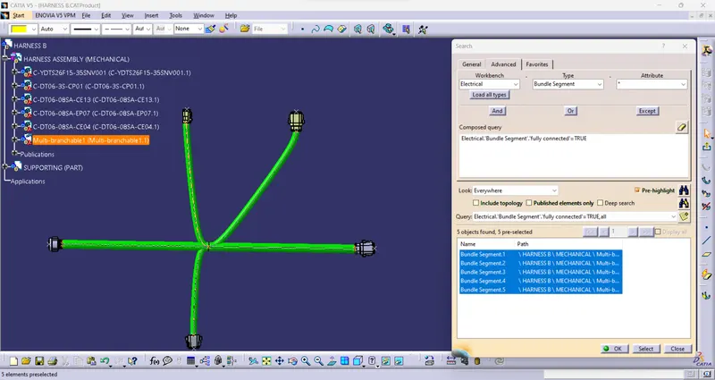
Check the bundle Continuity:
- Completely connected to all connectors and bundles.
- Check the connector and bundle are completely connected or not.
- Using the command "FULLY CONNECTED"
- TRUE= Fully connected bundles.
- FALSE=Not connected bundles.
- Show the result.
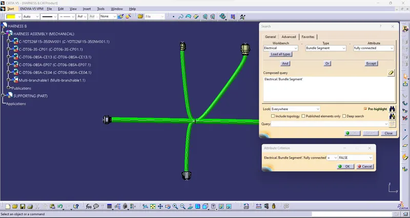
ADD PROTECTION:
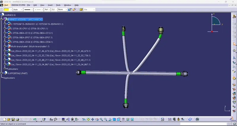
- Providing Corrugated tubes for protection for the bundles.
- Providing various size tubes.
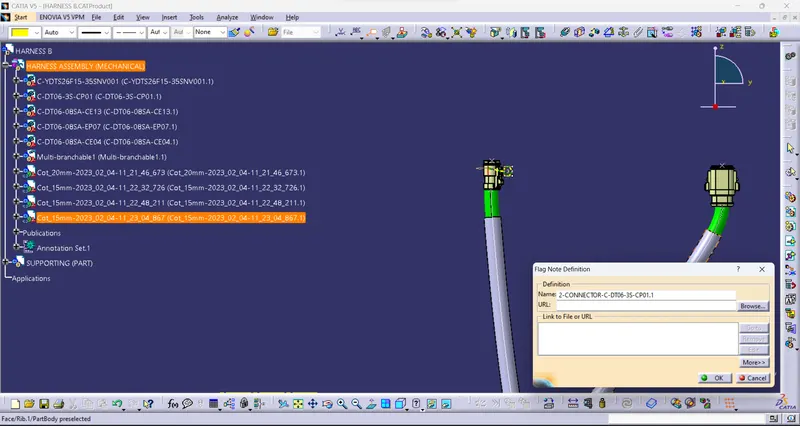
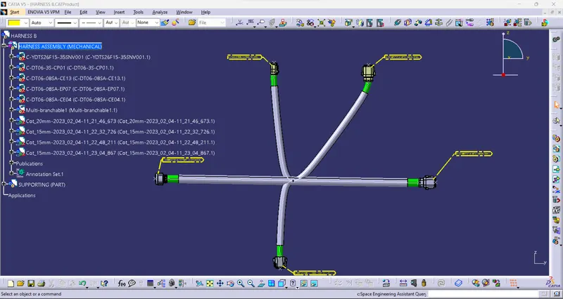
3D ANNOTATION:
- The 3D annotation is used on the wiring harness to show the connector function and additional notes.
- This annotation is to be added to the harness data to show specific information relating to the harness (wire type, wire spec, any additional information, and comments).
BUNDLE WARNING:
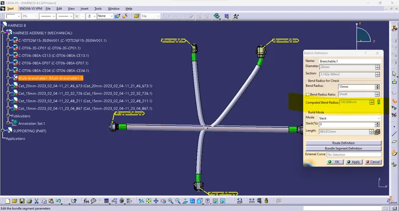
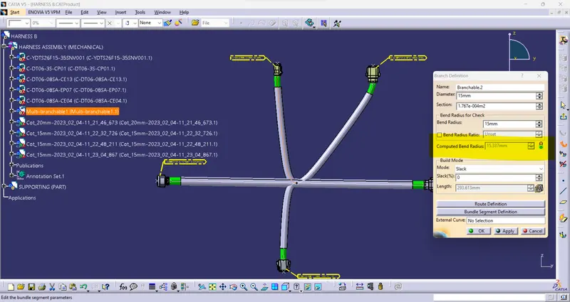
- These warnings are usually displayed in the structure of the wire harness geometrical bundle.
- it's usually related to the bend radius, bundle diameter, or the vector position of your bundle segments.
- If any issues are found the yellow flash warning symbol will appear in the tree structure of the geometrical bundle.
- Resolve the problem using the following:
- Change the supporting clips' location/ direction.
- Update new vector points.
- Add to slack to solve the problem for some time.
- Update branch point direction.
- Provide a new supported curve using Tangent management and From curve.
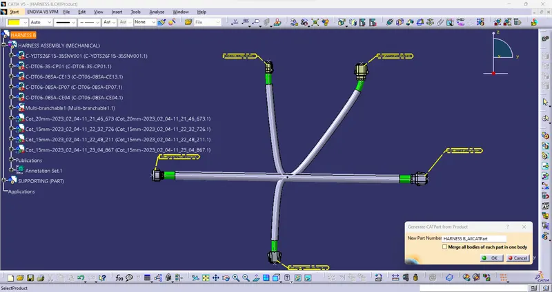
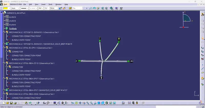
Generate CAT.part of harness assembly and convert is in. igs format
- It is sometimes used to be represented by some other tools (NX-CAD, CREO, etc.,)or lower vision Catia software.
- Create the CAT.part and convert the IGES or STEP file for the given requirements.