Wiring harness design in CATIA V5 - 3D modeling Week 5 & 6 Challenge
ANSWER:
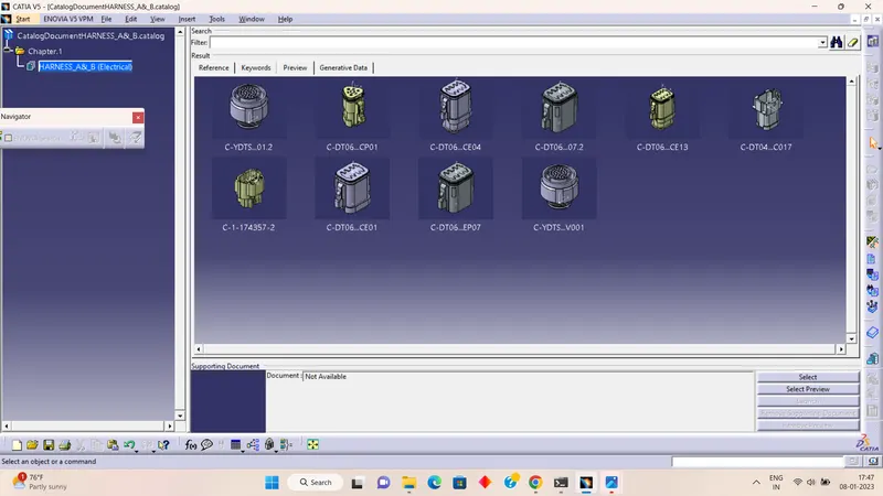
From the above-provided link, we have downloaded the required connectors to perform or create the harness assembly as shown above
We have to define all the mechanical components into the electrical component
Here we have defined them as given below
- Downloading the connector 3D part
- Creating the required geometrical parameters
- Define the part as an electrical connector
- Define bundle connection point
- Define connector connection point
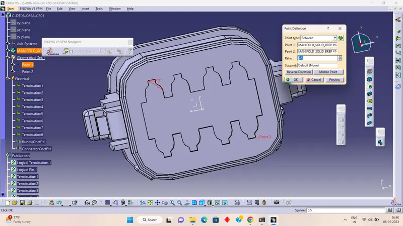
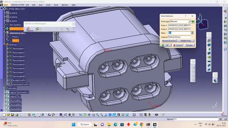
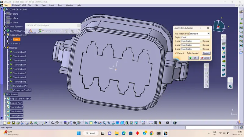
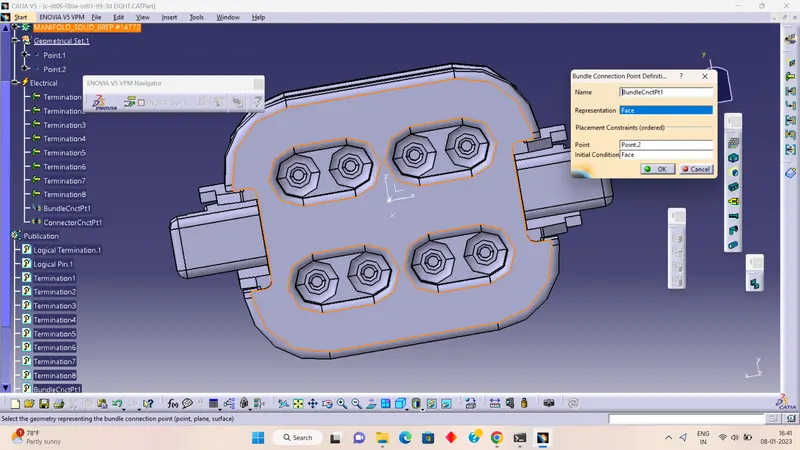
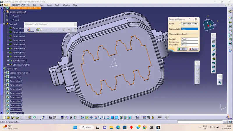
Like this, we have defined all the parts required to assemble.
Follow the below steps to create a geometrical bundle /harness assembly
- Create New Product File. First, we can click on file next select New and lastly select the product
- Again change the product part number to" Harness_A".
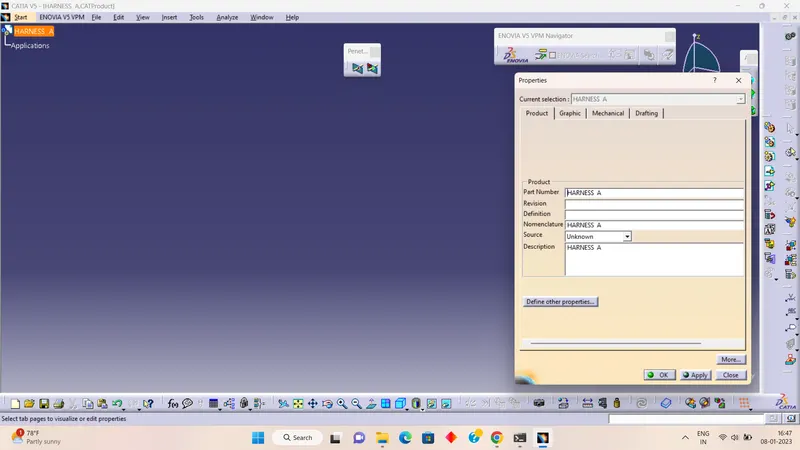
- When creating the wire harness bundle segment you are first required to insert the electrical components that you need to route the wire harness from and to.
- Before you can route the wire harness you will need an electrical definition.
- This data should also be removed from your context assembly before saving.
- By adding the required assembly connectors.
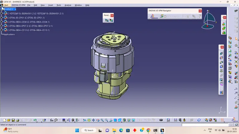
- There are five main functions for moving and positioning the electrical wire harness components. Those are in the assembly design workbench.
1) Manipulation.
2) Translation & Rotation
3) Snap
4) Smart Move
5) Compass
As well as we can use sketching to place them in the required position.
- Switch to the Electrical Harness Assembly Workbench icon.
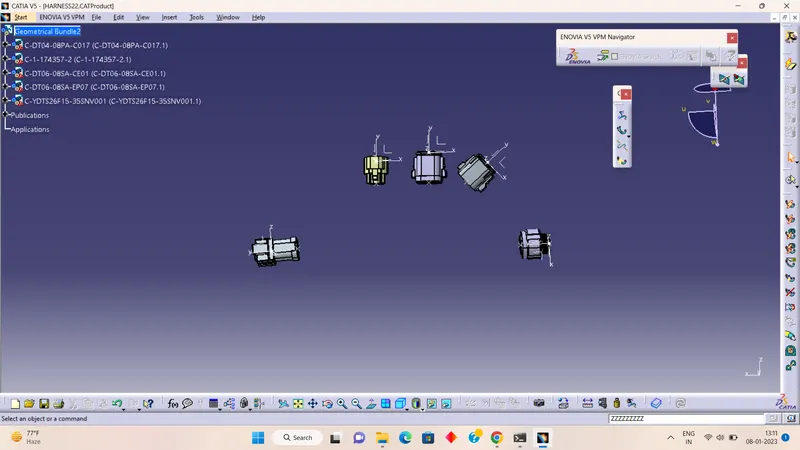
- Then select the Geometrical Bundle icon. Then select the product from the model tree(what we created) product icon in the model tree is changed now and the name changed to "Geometrical Bundle"
- Our assembly is changed from mechanical assembly to electrical assembly.
- Next we click on bundle definition the multi-breathable and publications are added to our assembly.
- You must now place each electrical part into its correct positioning in your geometrical bundle production file.
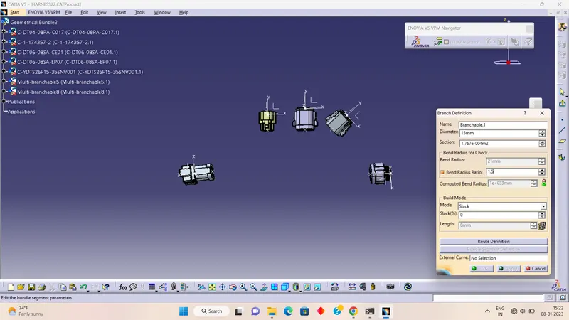
Then we click one bundle definition here we enter the diameter as 10mm and the bend ratio as 1.4 next clicks on the slack percentage as 0. Then click route definition here we can select the first connector and click add after then select another connector then click on a reverse tangent and click ok.
like this, we create multibranchable and branch breakpoints to complete the harness as we need
HARNESS B AS SHOWN BELOW
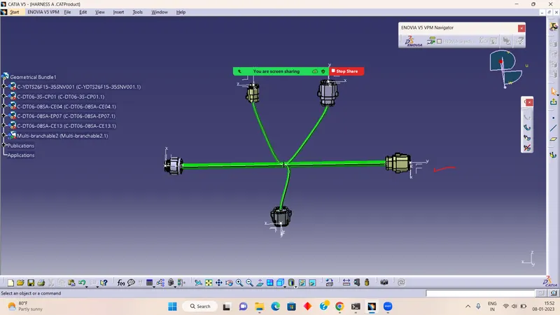
As an above procedure, we went for the HARNESS A
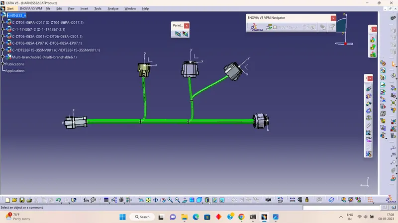
After completing both harnesses we check for continuity
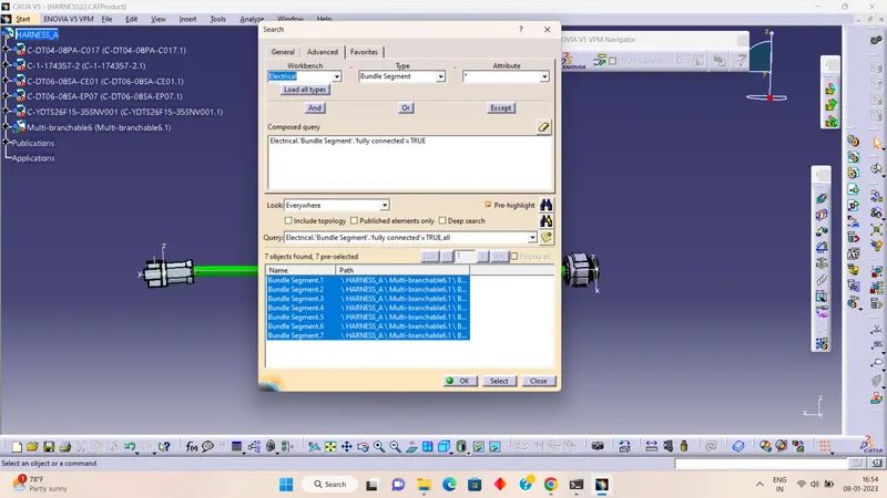
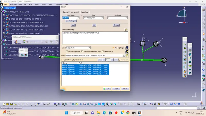
- To check the bundle continuity, click the edit button and search. Here new window will be displayed. Then we click on advanced.
- Here asking for some properties like workbench, type, and Attribute.
- In advance workbench select the electrical, type, we need to check the bundle segment continuity and attribute we need to check the fully connected.
- Here another window is pop up that is attribute criterion. Here we can find out which bundle segments are connected. Then we can select TRUE. Then click on ok and click on search
BELOW IS SHOWN FOR HARNESSING A
HARNESS B
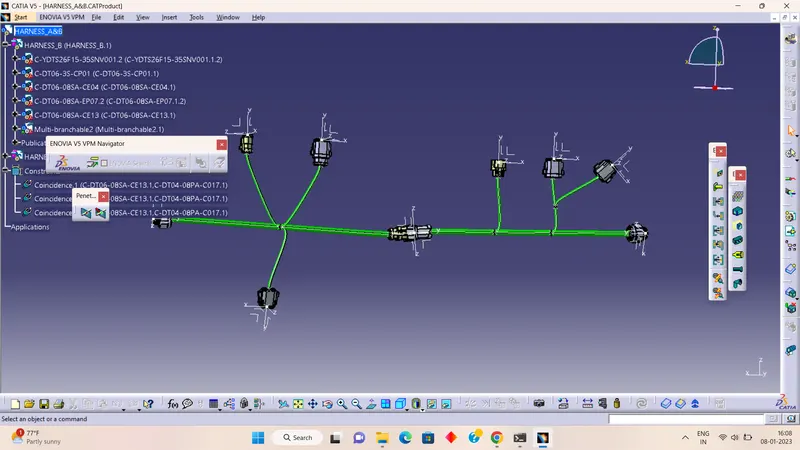
- AFTER THIS WE HAVE GONE TO HARNESS A & HARNESS B ASSEMBLY WE CREATED ANOTHER PRODUCT THAT INCLUDES BOTH HARNESS A AND HARNESS B.
- WE HAVE TO SWITCH TO AN ELECTRICAL ASSEMBLY DESIGN TO ELECTRICALLY CONNECT THE OPTION TO CONNECT THE ASSEMBLY WITH SPECIFIED CONNECTORS.
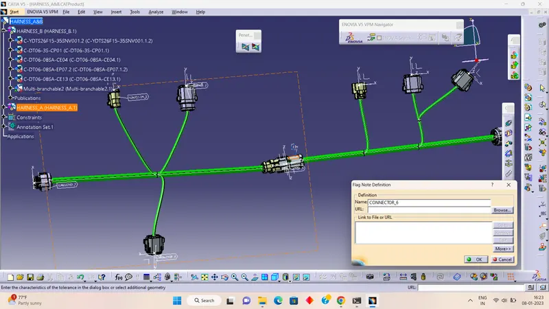
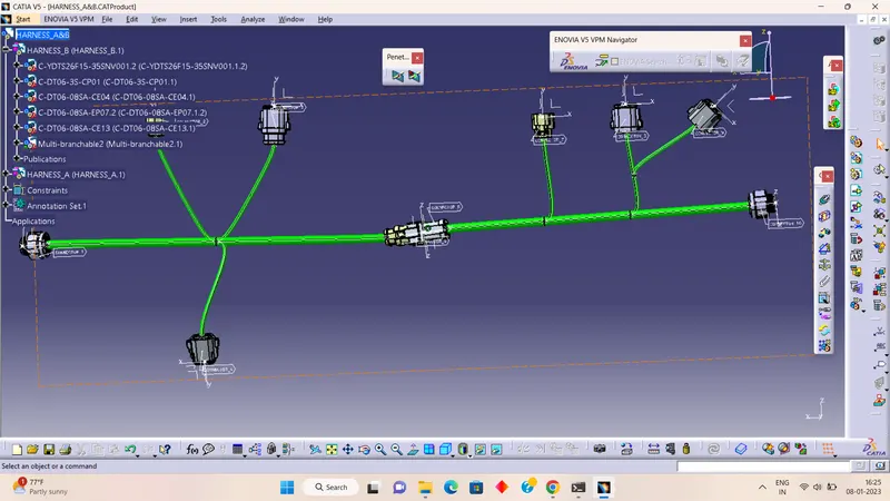
Then we have gone for the annotation as shown below
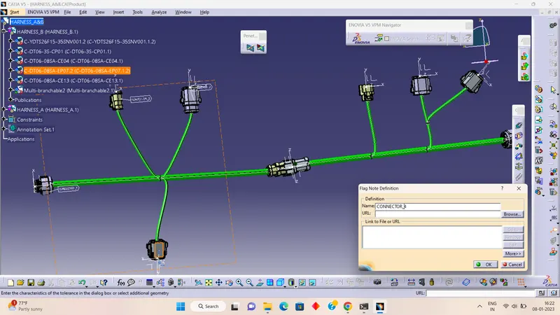
Add annotation to all connectors.
The 3D Annotation is used on the wiring harness to show the connector functions and additional notes.
Connector function annotation:-
This annotation is to be added to the connector to show the function of the connector /unit it is connecting to. This is used fully for other design departments that require the 3d harness models but are unfamiliar with the harness connector function.
Creating the Annotation:-
- Switch to the assembly design workbench.
- Make sure the geometrical bundle is active.
- Select the front view/annotation plane icon.
- Select the plane you wish to use for the annotation.
- Select the flag note with the lader icon.
- Select a reference point on the part to which you wish to add the annotation.
- Input the connector function (unit name)in the name definition and select ok.
CATALOG FOR CONNECTORS: