Wiring harness design in CATIA V5 - 3D modeling Week 5 & 6 Challenge
AIM
- Route two electrical harnesses as per the given layout and then check for bundle continuity, bundle warnings, and then give annotations to the final harness assembly and change the assembly into cad part
INPUT
PROCEDURE
Step 1
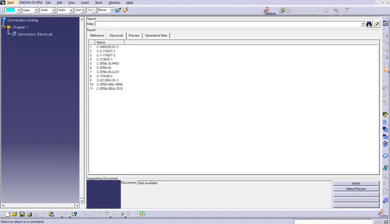
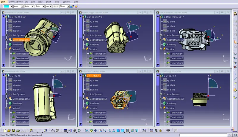
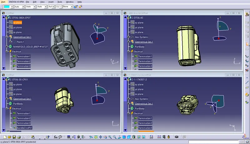
- Define all the electrical connectors geometrically and electrically
Step 2
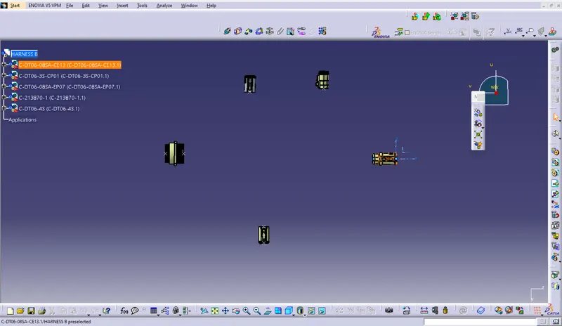
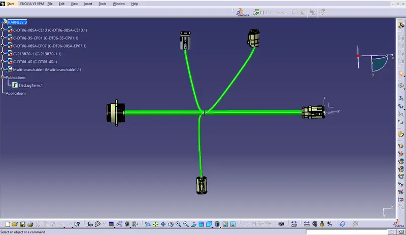
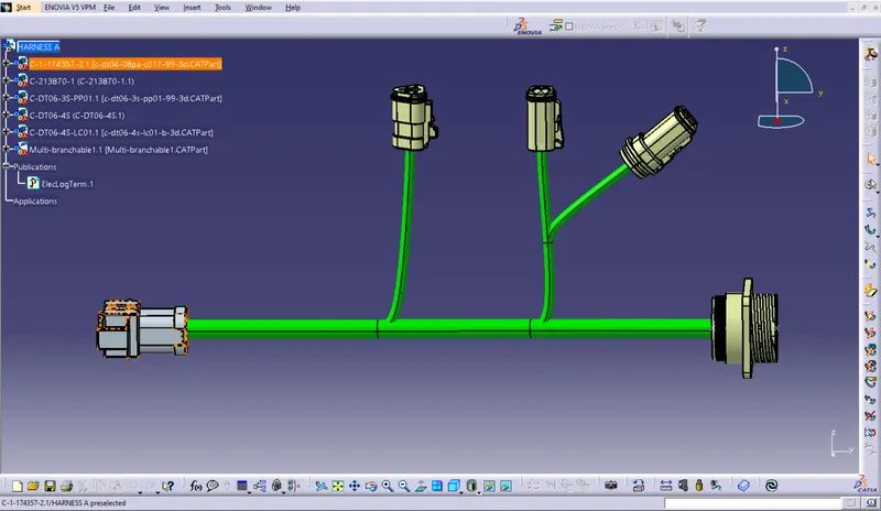
- Create harness A and harness B using the electrical harness workbench.
- First, all the connectors are placed at their desired locations. Second, bundle segments are created between the connectors with branch points and branches
Step 3
-
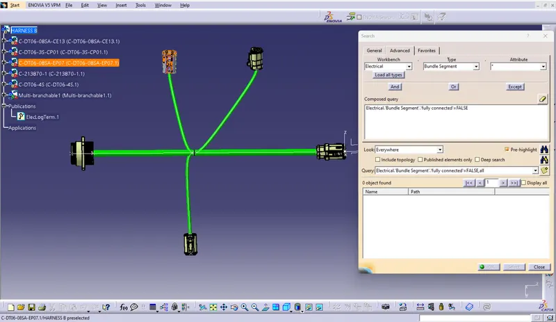
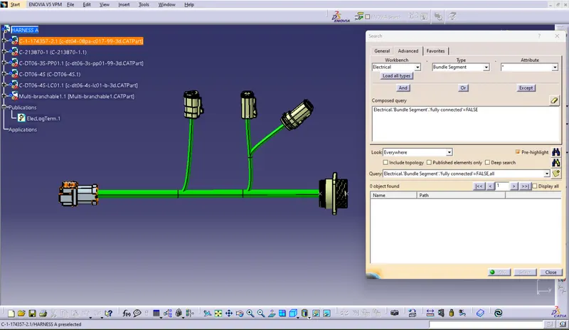
After Harness A and Harness B are created the next step is to check the bundle continuity.
-
First, we have to make sure multi-branchable is selected and then we have to go in Edit>Search>Advanced>Electrical Workbench>Type-Bundle Segment>Attribute-Fully Connected.
-
Selecting the "FALSE" option will show all the connected bundle segments while selecting the "FALSE" option will show all the non-connected bundle-segments.
Step 4
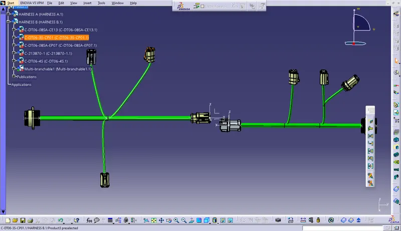
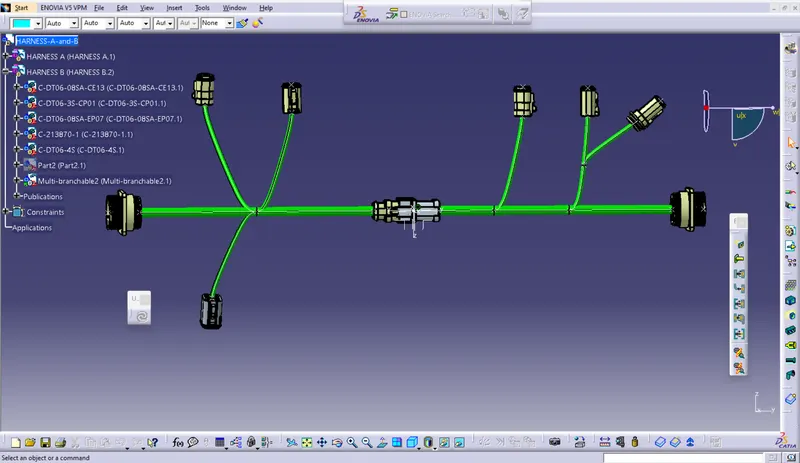
- In this step, we have to interconnect the Wiring Harness A and Harness B electrically.
- copy both harness A and harness B and paste it into the newly created product file to make the final harness assembly.
Step 5
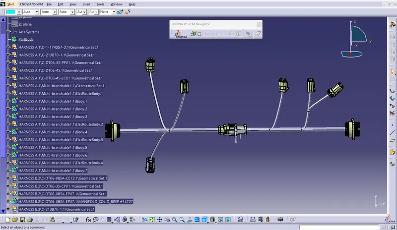
- In this last step we have to convert out Final Harness Assembly file into IGS format.
- The CAT part is created the whole product file is converted into a single part.
CONCLUSION
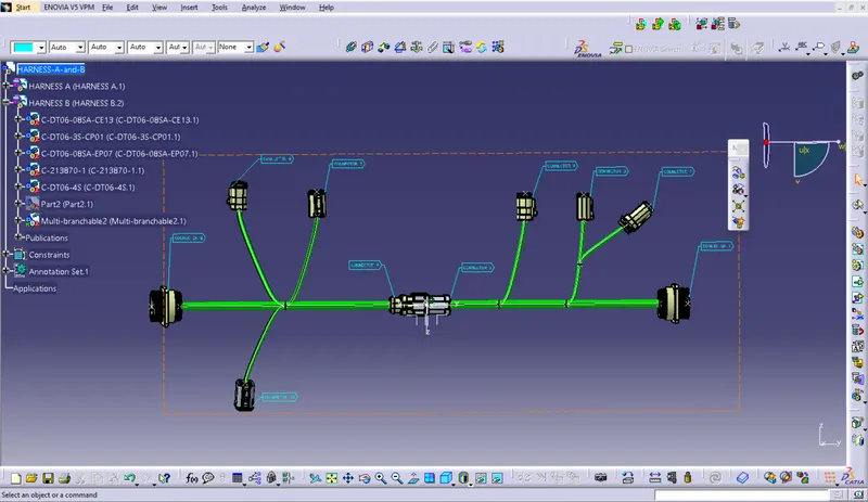
- Routing of the two electrical harnesses as per the given layout was achieved and interconnection between them as a single harness assembly was established. Both the harness were checked and corrected for bundle warnings and bundle continuity. At the very end, annotations were added to all the connectors and the final harness assembly file was converted into IGS format.