Week 8 - Challenge 2 - Switch Bezel Design
DESIGN AND DRAFT ANALYSIS OF SWITCH BEZEL 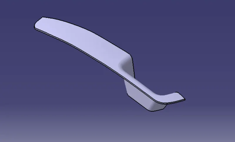
AIM: To create a switch bezel component through the given class A surface
Design methodology
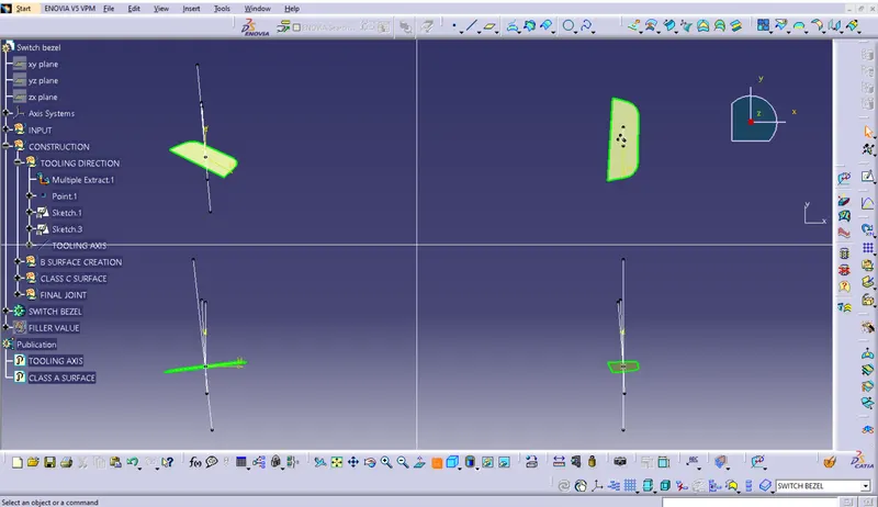
creation of tooling axis:
- Class-A surface is first analyzed to create the tooling axis or tooling direction that molds pull apart in injection molding. Tooling direction is important for plastic product design as it decides direction for mold separation.
Draft Analysis:
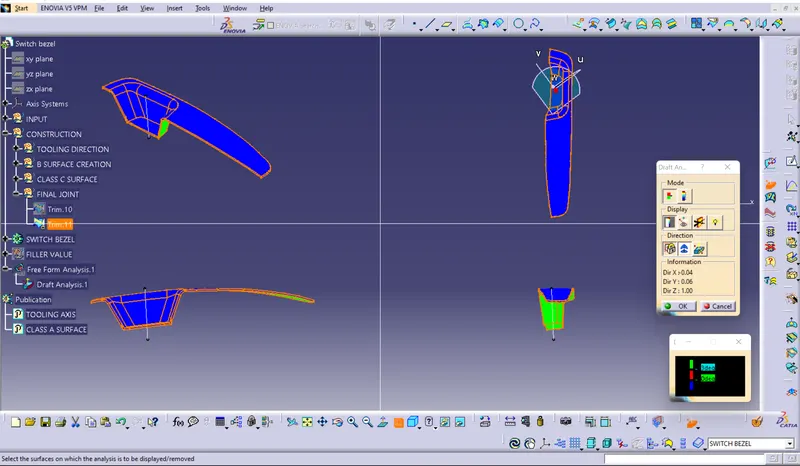
- The Draft angle is the amount of taper for molded or cast parts perpendicular to the parting line.
- A functional part for injection molding has to have drafts facing both cavity and core sides to reduce the risk of damage to the parts and ensure ejection.
- And also important is to overcome the vaccume forces by letting air in between the metal and the plastic for the part to release properly.
- Draft should be a part of design for manufacturing and plastic product Designer should be aware of its need at the outset of the design process.
- 3 Degrees is the nominal Draft angle.
Class B creation:
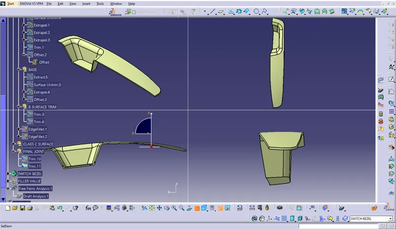
- To create the class be surface first we'll extract each and every surface of the class A surface except filleted surfaces.
- After extracting them individually we will untrim them to bring them back into their respective primary shapes.
- The untrimmed surfaces still don't intersect to each other completly so to intersect them completly we will extrapolate them with point continuity option.
- Then we'll give each and every surface with an offset value of 2.5mm (thickness of the model) in the downward direction.
- Finally we'll trim all the surfaces one by one untill we join all the surfaces into a single entity. After applying fillets(class A fillet radius - wall thickness) to the final trim, the resulting surface that we'll get will be called as the class B surface.
Class C creation:
- To begin with C surface creation we'll first extract the boundaries of the class A surface for this we'll use mutiple extract and selecting tangency propogartion. From this we'll get two continous curves.
- Since these two curves contains a lot of patches so to remove these patches we will smothen the extracted curves by using smooth command.
- Use sweep command and select "with draft direction" as the subtype, choose the smooth curves as the profile to sweep and choose the tooling axis as the draft direction.In addition to this give a draft angle of 3 degrees.
- Now extend the boundaries of the obtained sweeps using extrapolate command with boundary option.
- Finally trim both the sweeps with each other removing the extra part of the surfaces and joining them at the same time. The resulting surface we get is called the class C surface.
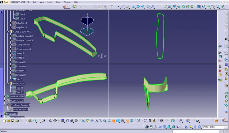
Final Output:
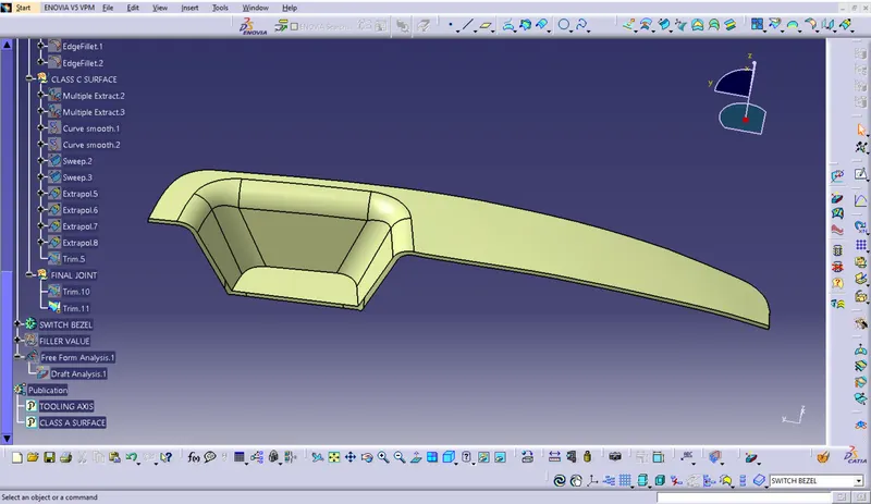
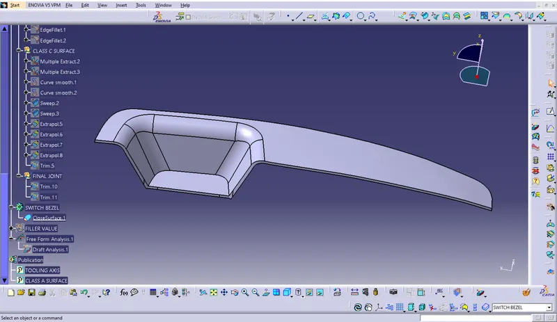
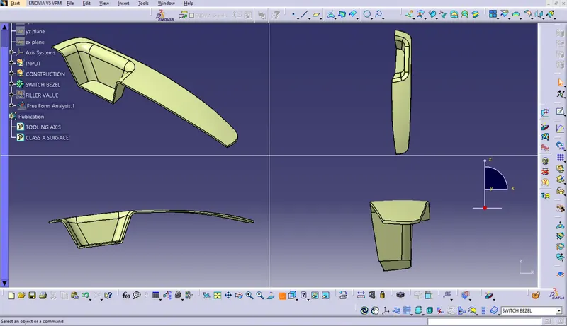
Tree structure:
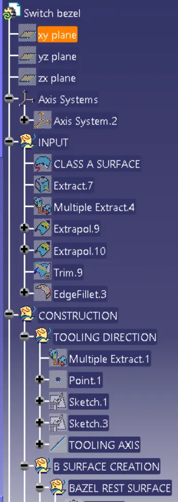
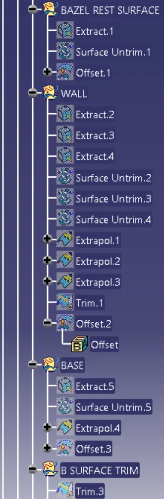
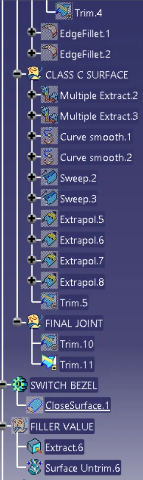
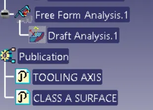
Conclusion:
- Hence the Switch Bezel plastic component through the given class A surface and created the required Tooling axis and performed the Draft analysis on the model and also for the solid model.