Photo Realistic Rendering
AMERICAN CHOPPER
OBJECTIVE:
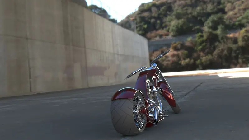
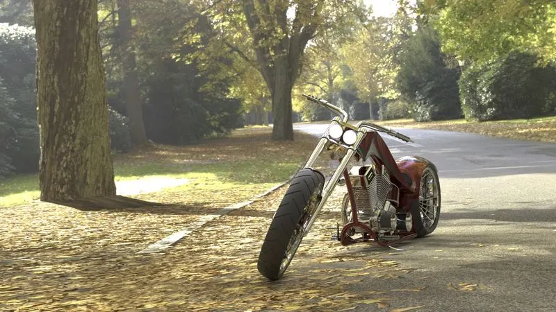
Creating an American Chopper Part models and Assemble the Part and Rendering the realistic model view of Chopper bike.
INTRODUCTION:
American Chopper Bike are motorcycles featured on the television series American Chopper build by Orange Country Chopper for a specific corporate or celebrity customer.
DESIGNING PROCESS OF CHOPPER
MODEL
↓
SKETCHING
↓
PART MODELLING
↓
ASSEMBLY
↓
RENDERING
DESIGNING PARTS OF CHOPPER:
- Transmission Belt
- Kick stand
- Front fender
- Rear fender
- Chain
- Oil tank
- Pedal
- Front wheel
- Rear wheel
- Front fork
- Chassis
- Engine
- Gas tank
TOOLS AND FEATURES USED:
- Sketch Entities.
- Line, circle, rectangle, arc, slot, spline.
- Convert entities- Create one or more curves in a sketch by projecting an edge, loop, face, curve or set of sketch curves on to the sketch plane.
- Trim and extend- Cut the point over the sketch entity and move the point over the sketch entity to extend.
- Offset-Offset line arc and splines if the original entity change the offset entity also change.
- Mirror- Mirroring is another way that can create copy of an existing object choosing a plane or mirror face.
- Pattern- Create multiple instances of one are more features that can space alone with pattern type.

- Features.
- Extrude-Extrude is a feature using to convert 2D sketch in to 3D model.
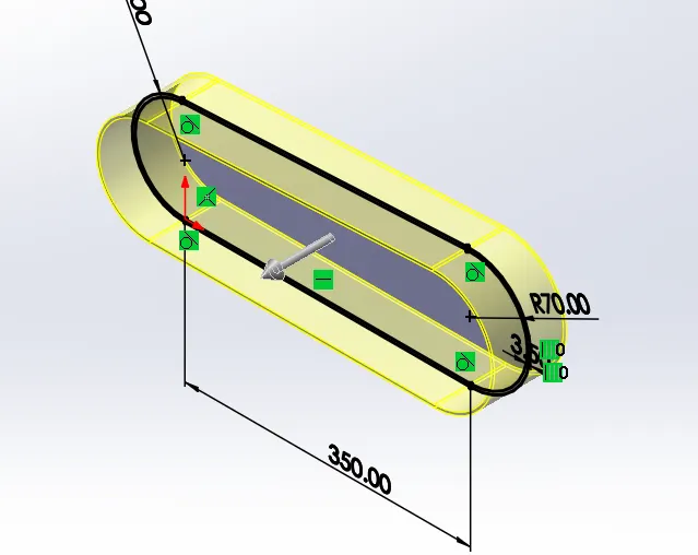
- Revolve- Revolves add or remove materials by revolving one or more profiles around a ceterline.it can create revolved boss/base, revolved cuts or, revolved surface. the revolved feature can be solid or a surface.
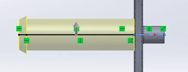
- Sweep- Sweep creates a solid, a cut or a surface feature by moving a profile along a path.
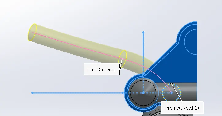
- Loft-loft feature creates a shape by making transitions between multiple profile and guide curves. this tool is very valuable for modelling complex surface.
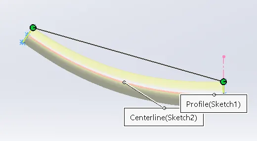
- Plane- Plane is reference for sketching and creating features.
- Curves-Curve as the path or guide curve for a sweep and loft feature, as a parting line for a draft feature.
CREATION OF THE CHOPPER PARTS
- Transmission belt:
- Sketch=tool→ sketch entities→ line
- Offset=tool→ sketch tool→ offset
- Boss extrude=insert→ boss/base→ extrude
- Fillet-create a rounded internal or external face on the part. selected faces, edges or edge loops (insert→ feature→ fillet)
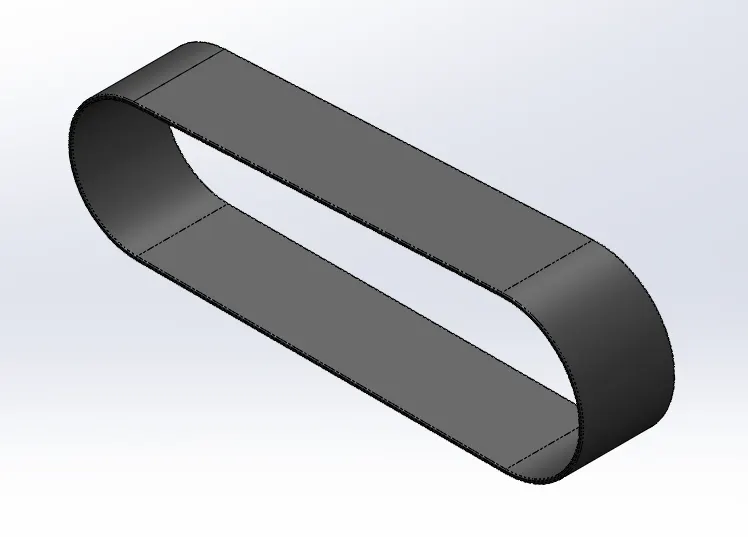
- Belts are mechanical elements used for power transmission without phase shift..
- Kick stand:
- Loft=insert→ boss/base→ loft
- Dome-it creates a dome that is tangent to the adjacent cylindrical or conical face (insert→ feature→ dome)
- Cut extrude=insert→ cut→ cut extrude
- Boss Extrude
- Fillet
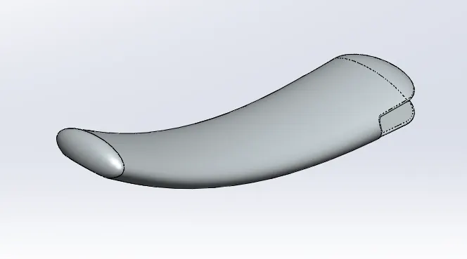
- A kickstand is a device that allows to rest a bike in an upright position.
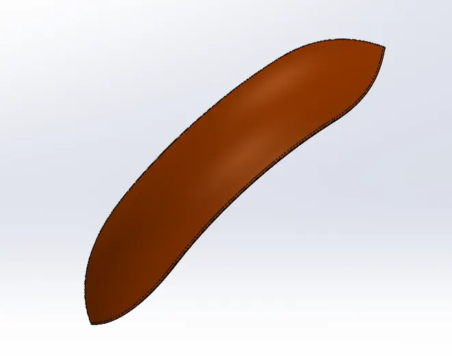
- Front and rear fender:
Front fender
- Revolve=insert→ boss/base→ revolve
- Split-use the split feature to create multiple parts from an existing part (insert→ feature→ split)
- Fillet
Rear fender
- Revolve
- Split
- Fillet
- Shell-the shell tool hollows out a part, leaves open the faces you selected, and creates thin feature on the remaining faces (insert→ feature→ shell)
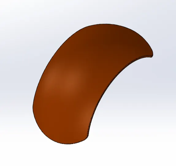
- The pressed and formed sheet-metal part mounted over the road wheels of a motorcycle, to reduce the splashing of mud.
- Chain:
- Extrude
- Fillet
- Circular pattern
- Mirror=insert→ pattern/mirror→ mirror
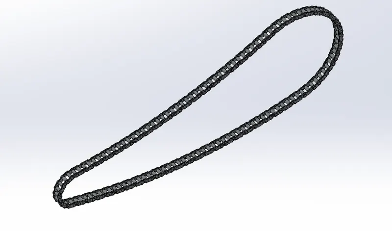
- Chains are more complicated than might expect with up to 116 links in a standard bike chain.
- The chain is actually most crucial link in the chopper model.
- Oil tank:
- Extrude
- Combine-multiple bodies contained within one multibody part file (insert→ feature→ combine)
- Fillet
- Shell
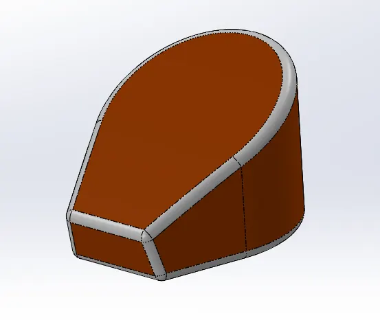
- The main function of the fuel tank is simply to hold fuel.
- Pedal:
- Extrude
- Fillet
- Revolve
- Dome
- Chamfer
- Linear pattern
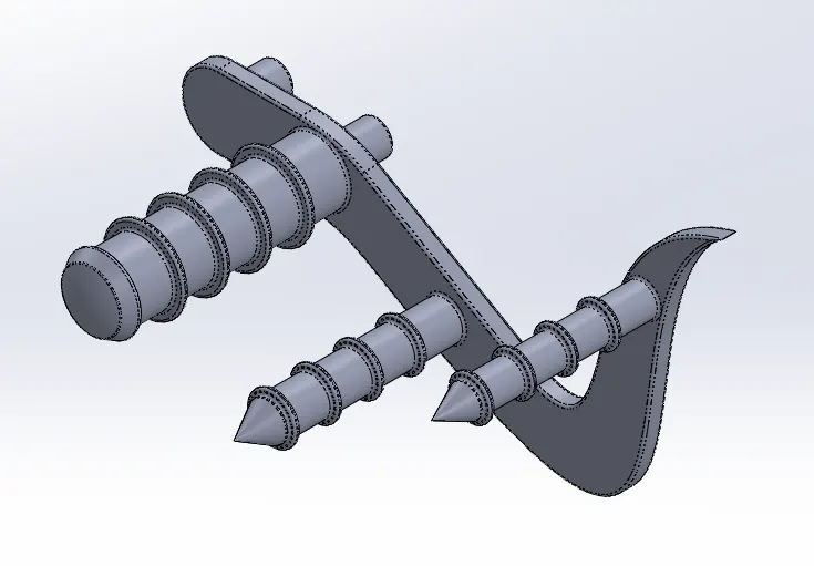
- Pedal is the external part to attached with chassis to using for rider comfort.
- Front and rear wheel:
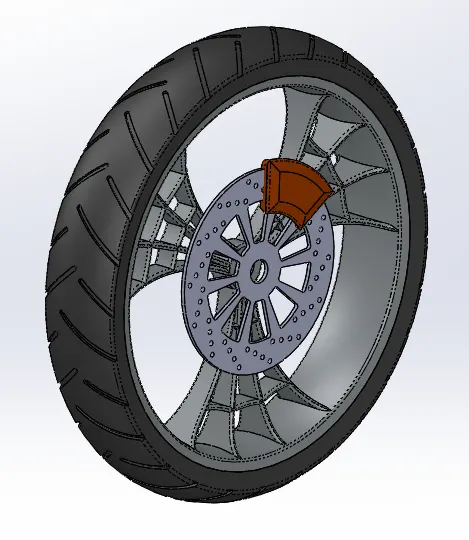
Front wheel
- Revolve
- Boss Extrude
- Cut extrude
- Cut revolve
- Circular pattern
- Combine
- Fillet
- Chamfer
Rear wheel
- Revolve
- Boss Extrude
- Cut extrude
- Combine
- Cut revolve
- Circular pattern
- Fillet
- Chamfer
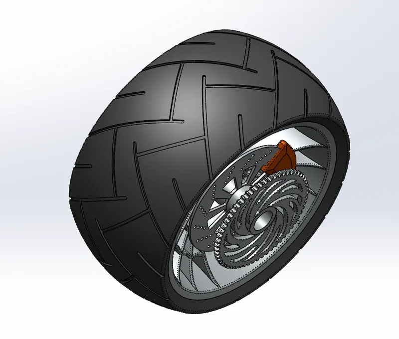
- A wheel is a circular component that is intended to rotate on an axle bearing.
- The wheel is one of the key components of the chopper model.
- Front fork:
- Revolve
- Boss Extrude
- Fillet
- Linear pattern
- Cut extrude
- Dome
- Cut revolve
- Curve
- Sweep
- Mirror
- Combine
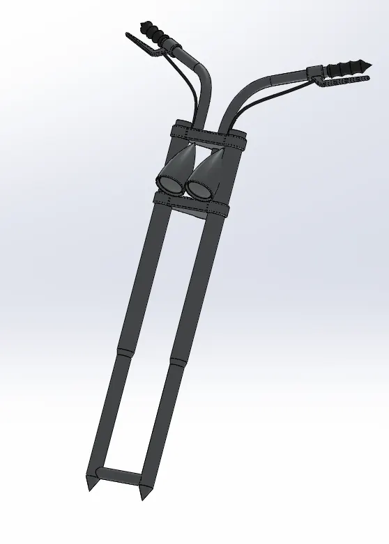
- It is comprised of 2 struts that connect the front wheel to the frame's head tube.
- Front fork look is the identification of the chopper model bikes.
- Chassis:
- Chopper blue print-A blueprint the template that use for all of drawings for a reference (tool→ sketch tools→ sketch picture)
- curve
- sweep
- mirror
- Boss Extrude
- Fillet
- Chamfer
- Split
- Combine
- Cut extrude
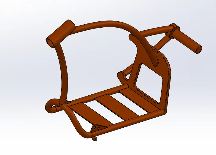
- Chassis, also known as 'Frame', is the foundation structure of bike that supports it from underneath.
- The purpose of the chassis is to bear the weight of the car in its idle and dynamic states.
- Engine:
- Blue print engine
- Boss Extrude
- Fillet
- Revolve
- Circular pattern
- Dome
- Cut extrude
- Chamfer
- Mirror
- Split
- Sweep
- Composite curve
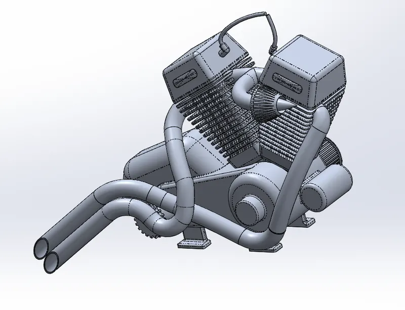
- A motorcycle engine is an engine that powers a motorcycle.
- Motorcycle engines are typically two-stroke or four-stroke internal combustion engines.
- I personally engine part is the so much time for designing.
- In the model I can learn about the sold modelling and curves very much.
- Gas tank:
- Surface sweep
- Surface trim
- Curve
- Surface loft
- Boundary surface
- Mirror
- Surface knit
- Split line
- Cut sweep
- Fillet
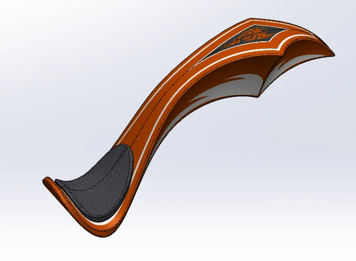
- Surface model is an alternative to solid body model.
- Essentially, it's just another tab at the top of the SOLIDWORKS User Interface.
- Surface model is an important tool to have in your box because it not only makes model easier, it sometimes makes model possible.
- Gas tank is the surface model in the chopper.
ASSEMBLY:
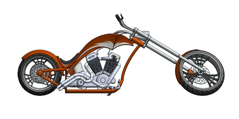
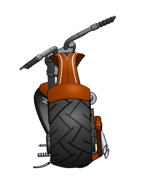
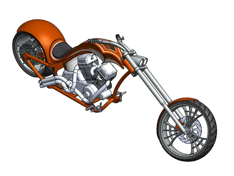
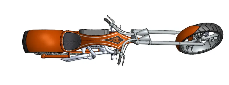
- Assembly is the process of combining individual components into one feauture design.
- Can create assemblies using bottom-up design, top-down design, or a combination of both methods.
- Using mates for assembly process.
- Assembly → insert part→ select a base part→ fix the part→ connect all the part using mates→ save the assembly
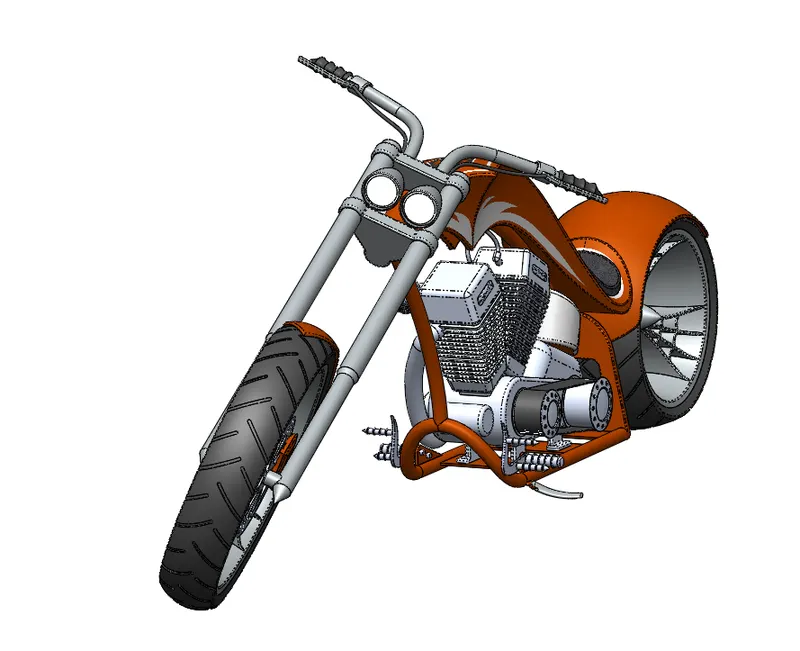
Mates
- Mates are constraints that hold components together in SOLIDWORKS assemblies.
- Mates has 3 type of standard mates, advanced mates, mechanical mates.
- Standard mates include angle, coincident, concentric, distance, lock, parallel, perpendicular, and tangent mates.
- Advanced mates include limit, linear/linear coupler, path, profile center, symmetry, and width mates.
- Mechanical mates include cam-follower, hinge, gear, rack and pinion, screw, slot and universal joint mates.
- Chopper model mainly using only standard mates.
APPEARANCE AND DECAL:
Appearance
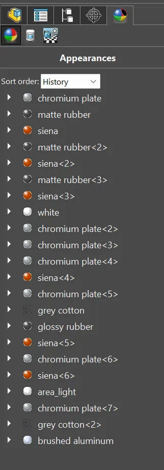
- To add an appearance, select the desired appearance in the appearance tab of the Task Manager.
- Left drag onto the model and hover over what you would like to apply the appearance to.
- Select Face, Feature, Body, Part or Assembly from the selection bar.
- Chopper model I am using metal, rubber and light appearance.
Decal
- Apply a decal.
- In the Display Manager, click View Decals, right-click a decal, and select Edit Decal.
- Right-click the decal on the part, click Appearances. and select the decal.
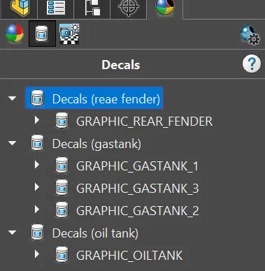
Photo view 360
- With a model open, click Tools > Add-In and add in Photo View 360.
- Edit appearances, the scene, and decals.
- Edit lights.
- Edit camera option.
- Edit Photo View Options.
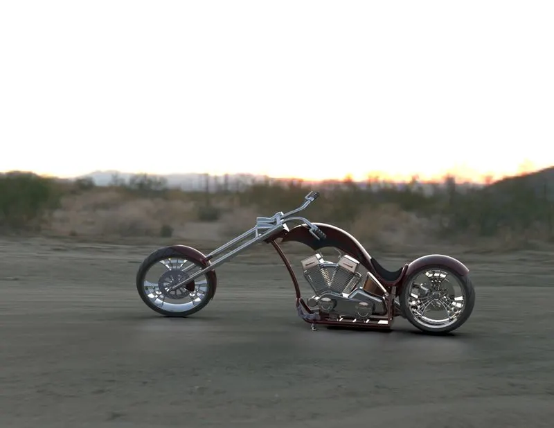
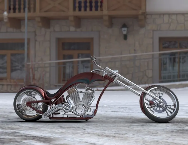
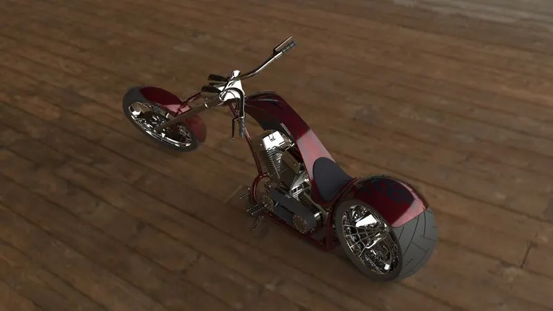
PHOTO REALISTICS RENDERING:
CONCLUSION:
In this chopper model I am using various type of 2d sketch ,3d feature, assembly tool, appearances, decals, various views and photo real look chopper model.