Wiring harness design in CATIA V5 - 3D modeling Week 5 & 6 Challenge
Aim:Route the following harness layout in Electrical workbench. Make assumption for harness bundle diameters. Use the connectors provided. After completion of routing.
OBJECTIVE-
- The objective of this project is to first route the two Harness A and Harness B as per the given harness layout.
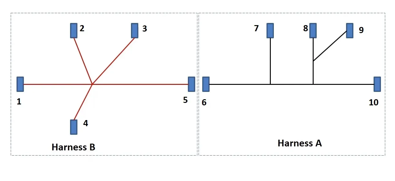
The electrical connectors are represented by numbers in the above figure. There are 8 different types of connectors at 10 different locations.
2. Bundle continuity has to be checked for the two created harness.
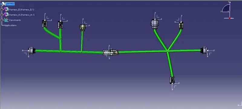
3. After the two Harnesses are created, the next objective is to have them interconnected electrically.
4. Check for bundle warnings in Harness A and Harness B.
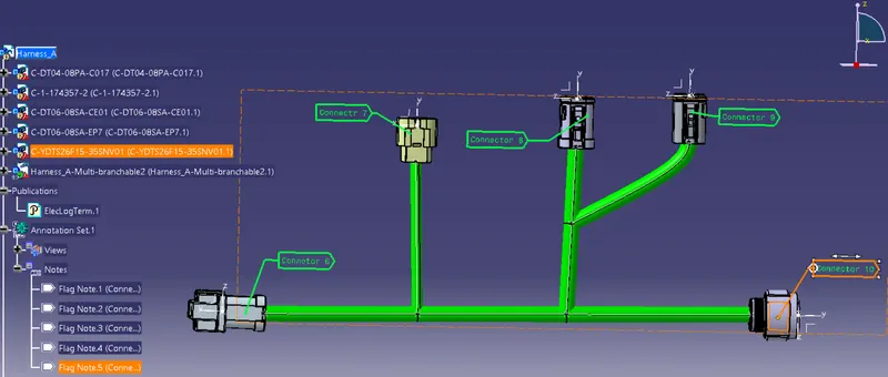
5. Add annotations to all the connectors in Harness A and Harness B.
6. The final objective of this project is to convert the final harness file into IGS file format.
CONTENT-
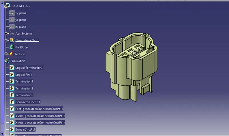
Define all the electrical connectors geometrically and electrically so that they can be used in the wiring harness.
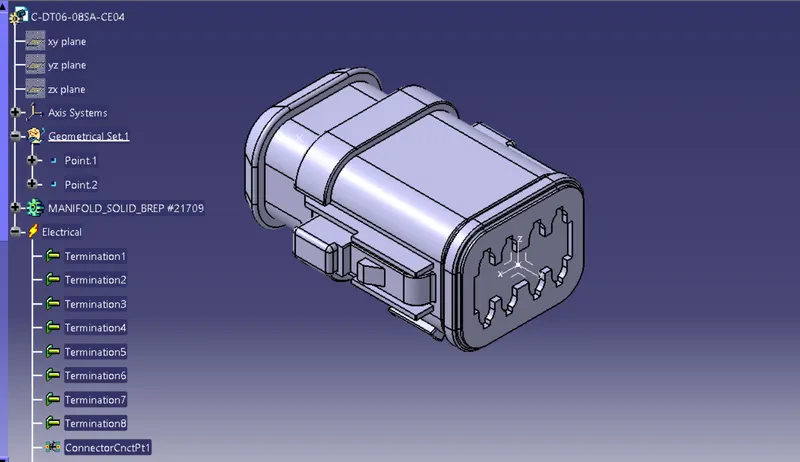
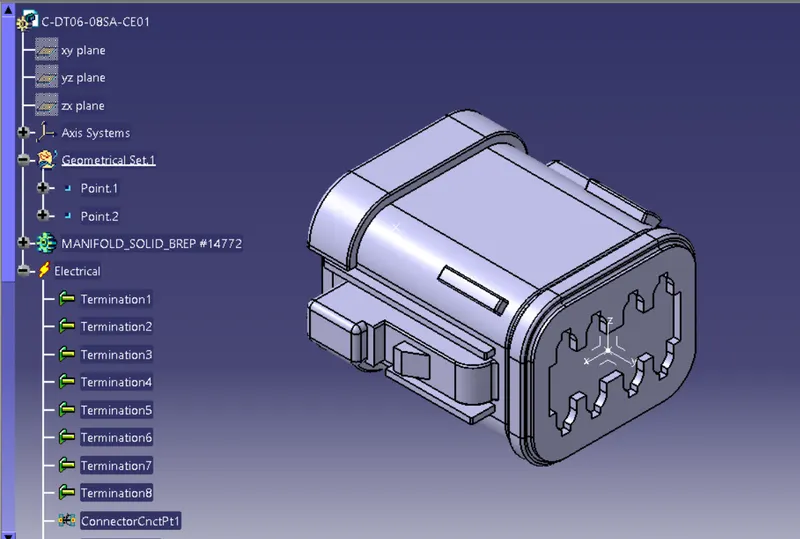
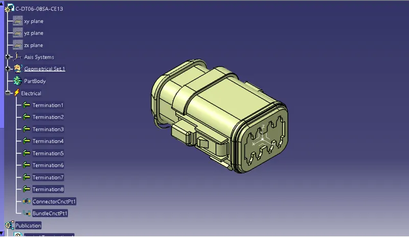
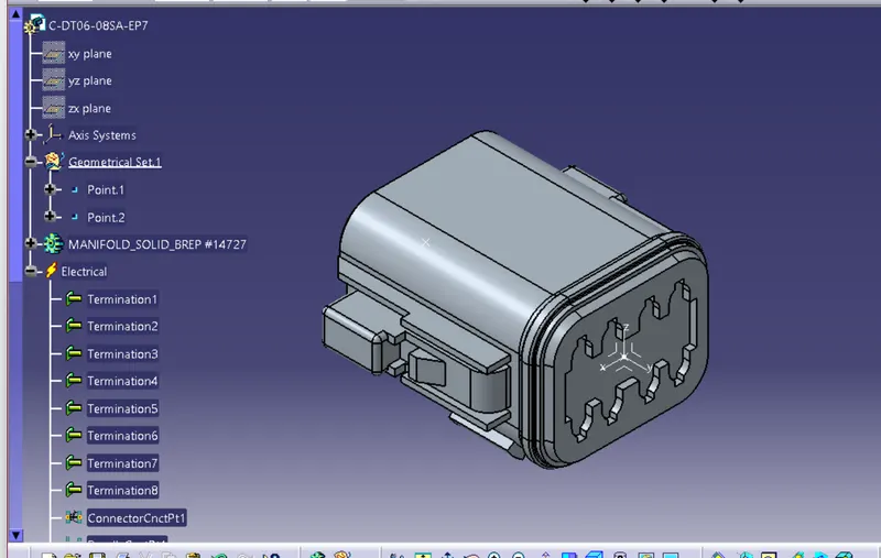
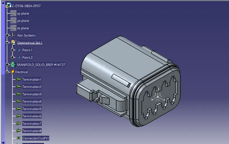
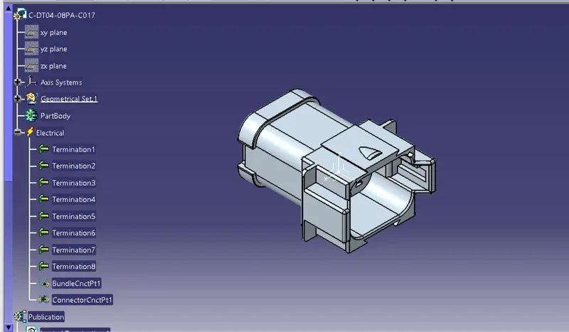
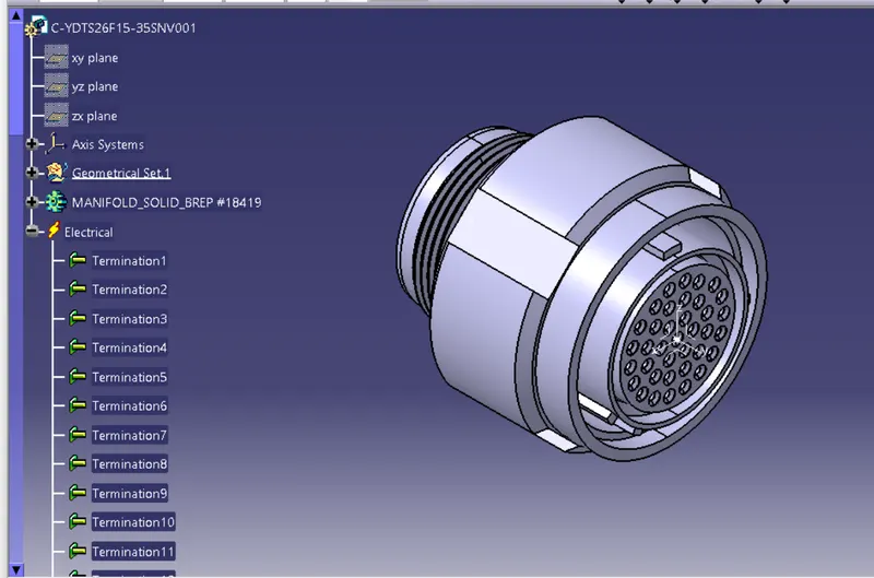
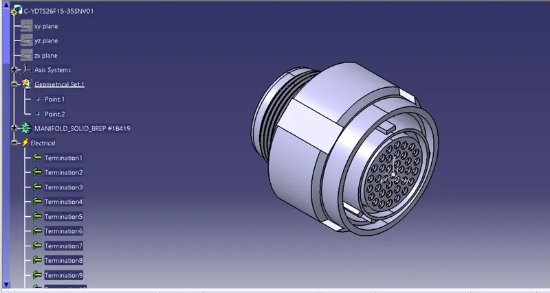
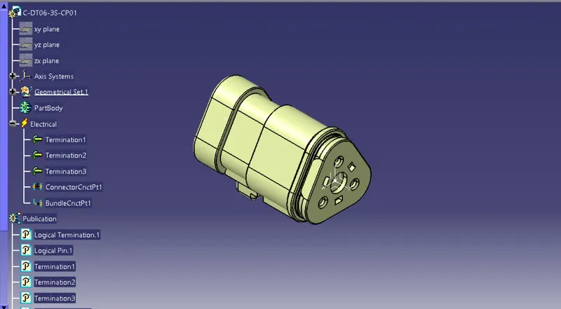
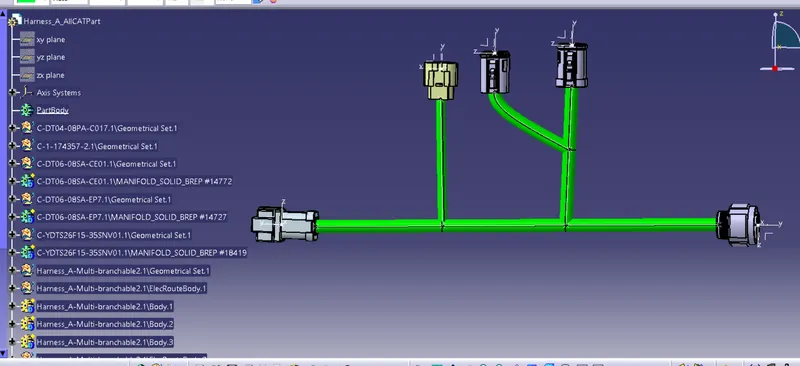
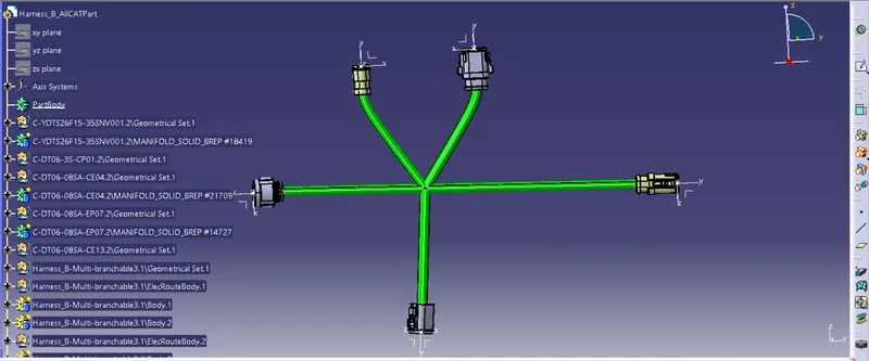
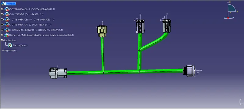
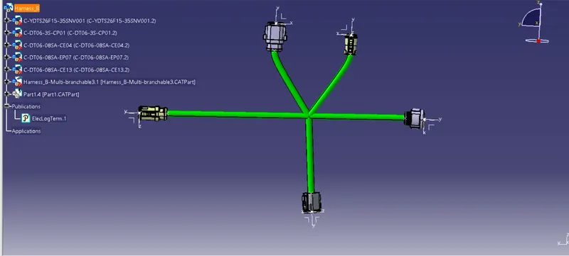
Create harness A and harness B as shown below by using the electrical harness workbench in CATIA V5.
First, all the connectors are placed at their desired locations. Second, bundle segments are created between the connectors with branch points and branches as shown below.
Bundle diameter is assumed to be 20mm, 15mm, 10mm, and 5mm for different bundle segments. Bend ratio is given as 1.4 and slack is given as 0% for all the bundle segments.
Harness A:
Harness B:
After Harness A and Harness B are created the next step is to check the bundle continuity.
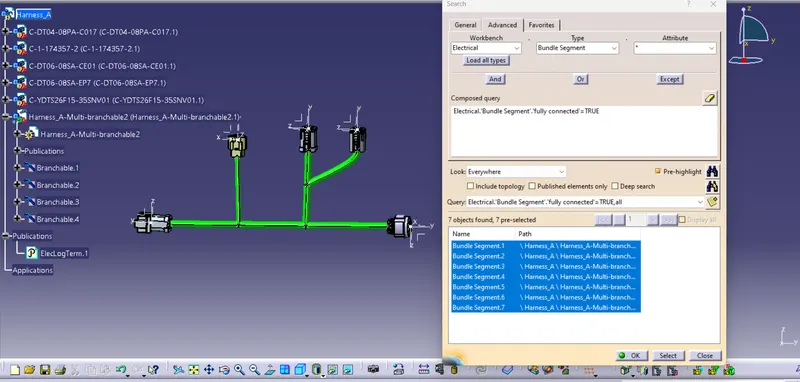
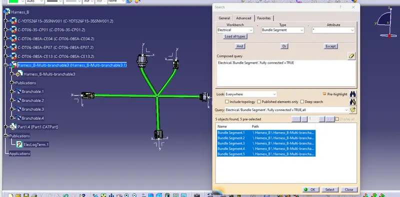
First, we have to make sure multi-branchable is selected and then we have to go in Edit>Search>Advanced>Electrical Workbench>Type-Bundle Segment>Attribute-Fully Connected.
Selecting the "TRUE" option will show all the connected bundle segments while selecting the "FALSE" option will show all the non-connected bundle-segments.
For now, we will select the "TRUE" option and search for results. All the bundle segments in Harness A and Harness B will be displayed showing that there is bundle continuity in Harness A and Harness B.
Harness A:
Harness B:
Interconnect the Wiring Harness A and Harness B electrically.
Checking bundle warning Harness A&B:
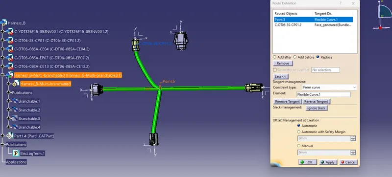
Geometrical bundle warnings are shown for Bend radius, Bundle diameter, Vector position. If these values or inputs are incorrect then the yellow flash will appear in the tree structure next to the branchable with problems. Depending on the route of the bundle segment we can correct the issue by adding some extra slack or by changing vector position of the segment point. In our case, we have one error as shown below in Harness B in "branchable 3"
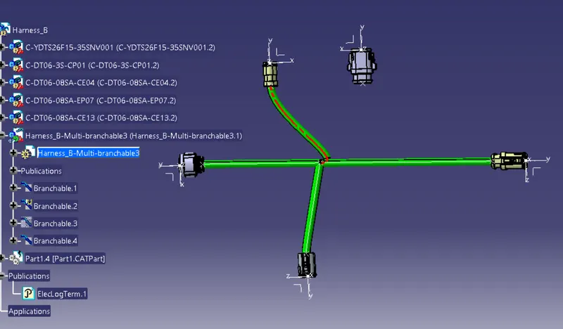
This error can be corrected by changing the direction of routing. We should "reverse tangent" or change the direction of the routing at the branch point 4 as shown below.
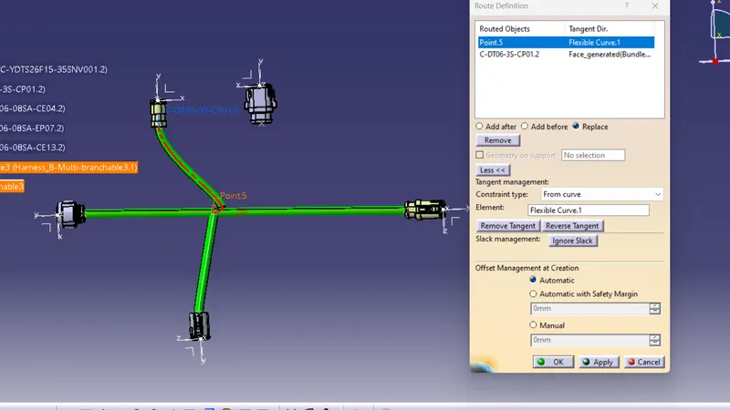
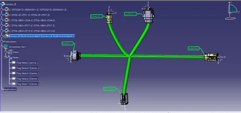
Adding annotations for all the electrical connectors.:
Harness B:
Harness A:
Generated The Harness Assembly to CAT.part & Convert is in. igs format.: