Wiring harness design in CATIA V5 - 3D modeling Week 5 & 6 Challenge
Downloaded all the files from the given data.
Created each part on part design workbench then defined them electrically on electrical part design workbench.
Here is the Snapshot for the harness A in given mapping data:
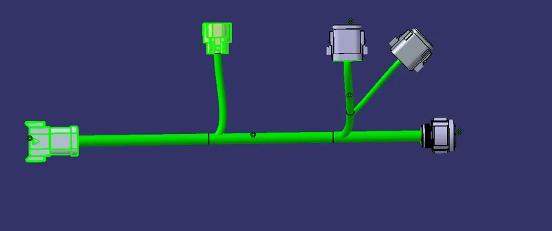
HARNESS A
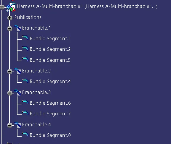
Checking for continuty .
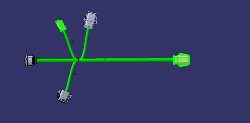
HARNESS B:
Checking for continuety:
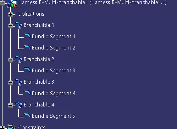
So after preparing both the assambly. There was no error in any part or assmbly.
Both the products are mapped according to the given data as well as the part number.
Connected both of the product together electrically as well as mechanically usning Electrical wiring assambly workbench.
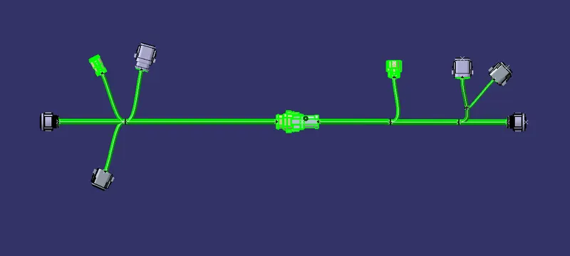
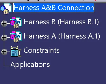
The tree structre was also updated.
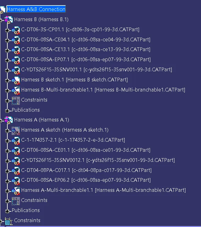
Final overall tree structre looks like this.
Converted my files into IGES format as required.
All files are arranged in a particular manner with folder names.
The zip file is attached below.
Kindly look for "Harness A&B" folder for the final assambly. The iges file also in that folder.