Wiring harness design in CATIA V5 - 3D modeling Week 5 & 6 Challenge
AIM
Route two electrical harnesses as per the given layout and interconnect them as a single harness assembly and then check for bundle continuity, bundle warnings, and then give annotations to the final harness assembly.
Software Used
Catia V5
Introduction
CATIA® is the world's engineering and design leading software for product 3D CAD design excellence.It is used to design, simulate, analyze, and manufacture products in a variety of industries including aerospace, automotive, consumer goods, and industrial machinery
A wire harness, also commonly referred to as a wiring harness, is an exterior sheath used to cover some types of electronic wires. Generally, wiring harnesses are made of thermoplastic or thermoset materials that can help protect the cables from the environment. It is a low-cost, simple method for technicians to keep wires organized, protected, and easy to navigate. Although most wires come with their own exterior sleeves, those sleeves seldom are thick enough to protect the wires from dust, debris, and moisture. The thicker the wire is, the more risk there is of it sustaining damage due to a burned fuse.
The term “wire harness” is often used interchangeably with the term “cable assembly.” However, these are actually two different products. While both are exterior sheaths used to protect wires or cables, the cable assembly is made of a more durable material and is created to offer a higher level of protection in the most extreme conditions. Wiring harnesses and cable assemblies each have a distinct purpose in the electrical field. Selecting the right one is based on the application needed and is an important part of the success of your product. Ensuring that you have experienced, and informed members of your team helps ensure that you are using the correct components for your project.
Input
- The objective of this project is to first route the two Harness A and Harness B as per the given harness layout.
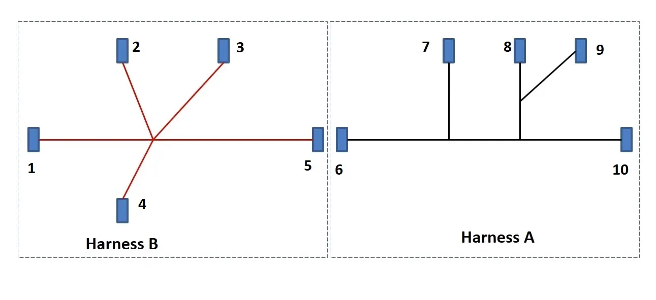
Figure 1: Shows the layout of two Harness A and Harness B
The electrical connectors are represented by numbers in the above figure. There are 8 different types of connectors at 10 different locations.
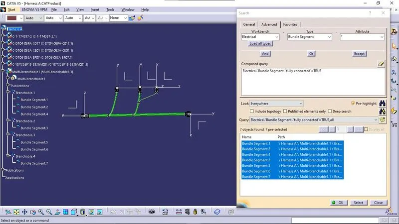
2. Bundle continuity has to be checked for the two created harness.
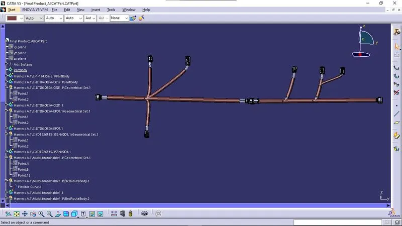
3. After the two Harnesses are created, the next objective is to have them interconnected electrically.
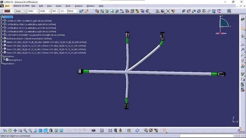
4. Check for bundle warnings in Harness A and Harness B.
5. Add annotations to all the connectors in Harness A and Harness B.
6. The final objective of this project is to convert the final harness file into IGS or stp file format.
Design Mathodology
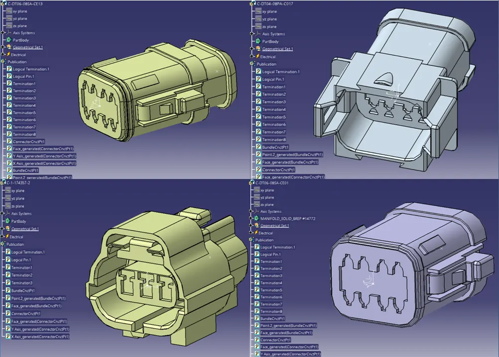
- Defining all the electrical components
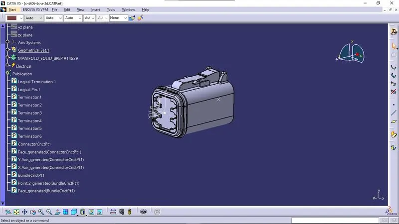
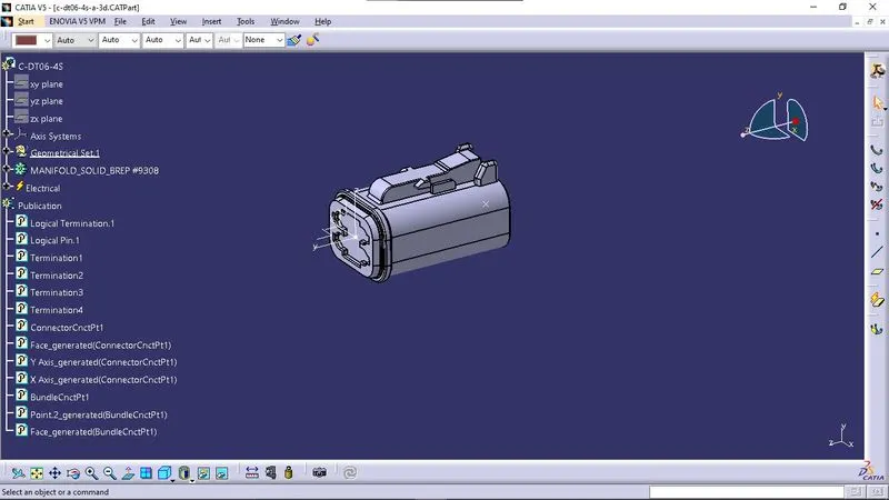
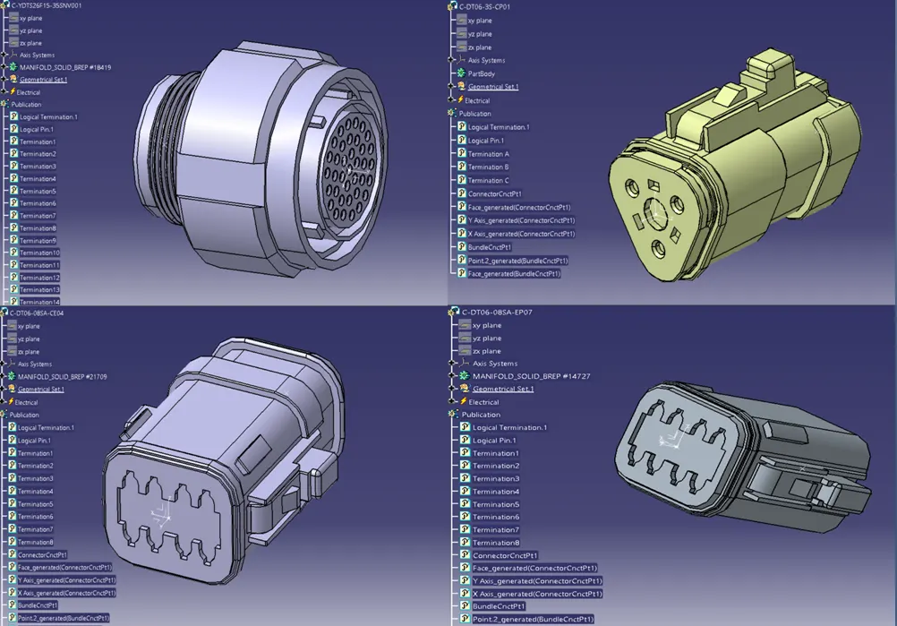
Harness A
Harness B
Final Output
Conclusion
Routing of the two electrical harnesses as per the given layout was achieved and interconnection between them as a single harness assembly was established. Both the harness were checked and corrected for bundle warnings and bundle continuity. At the very end, annotations were added to all the connectors and the final harness assembly file was converted into Stp format.