Wiring harness design in CATIA V5 - 3D modeling Week 5 & 6 Challenge
Week 5&6 Wiring Harness Design Challenge-:
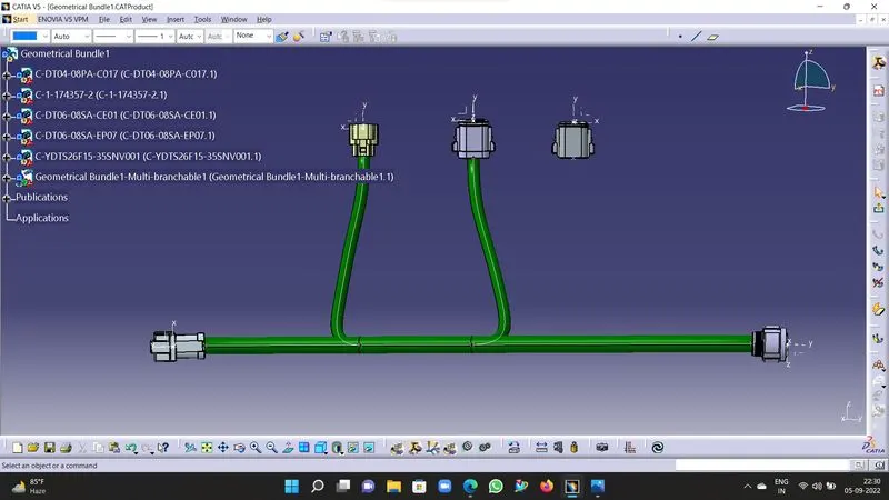
1. Introduction-: In this challenge we need to design & route wiring harnesses A&B as per the layout & check the bundle continuity, bundle warning, adding annotation sets & generate Cat.part & convert it in .igs file.
2. Wiring Harness B-:
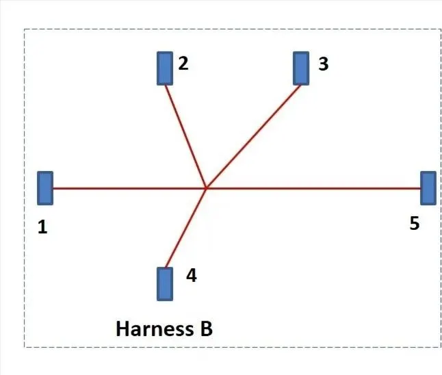
Procedure-:
- First create a product assembly.
- Add the connectors & required components.
- Position the connectors as per layout.
- Then switch to Electrical Harness Assembly design workbench.
- Define the product assembly as a geometric bundle.
- Then create a multi brancheable part file in it.
- Define the routing between connectors as per layout using branch points.
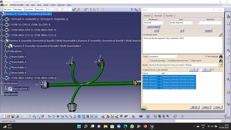
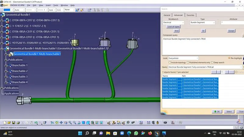
- Now check the bundle continuity.
- For checking click on Edit<Search<Advanced<Electrical<Bundle<Segment<Fully Connected<True/False.
- Then click on search button for the results.
- If choosen true and it highlights all the branch that means your assembly is fuly connected.
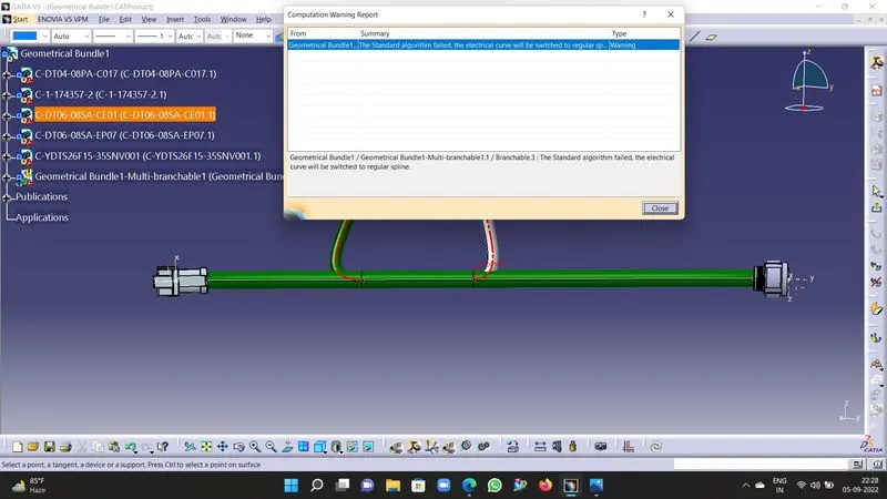
- Now check the geometric bundle warning.
- If warning shown it will be mostly of bend radius.
- We can resolve that by defining stack in branches, changing tangent, changing bend radius, or by repositioning of connectors.
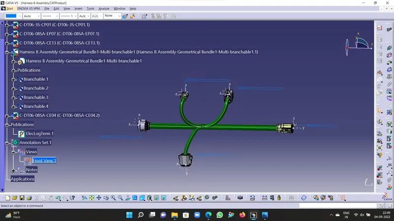
- Now to define annotations exit the multi-brancheable part file and switch to geomtric bundle.
- Switch to Assembly then choose the annotation style and define the each connector as per the desired properties to be highlighted.
- Now, to create geometric .Cat part from product assembly , open tools while in assembly workbench.
- Choose generate.Catpart option and define the part name click on, .Cat part will be generated.
- Save it & then change it to.igs format and save it again.
3. Wiring Harness A-:
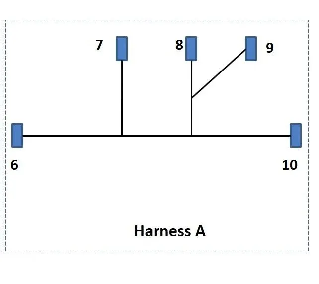
Procedure-:
- First create a product assembly.
- Add the connectors & required components.
- Position the connectors as per layout.
- Then switch to Electrical Harness Assembly design workbench.
- Define the product assembly as a geometric bundle.
- Then create a multi brancheable part file in it.
- Define the routing between connectors as per layout using branch points.
- Now check the bundle continuity.
- For checking click on Edit<Search<Advanced<Electrical<Bundle<Segment<Fully Connected<True/False.
- Then click on search button for the results.
- If choosen true and it highlights all the branch that means your assembly is fuly connected.
- Now check the geometric bundle warning.
- If warning shown it will be mostly of bend radius.
- We can resolve that by defining stack in branches, changing tangent, changing bend radius, or by repositioning of connectors.
- Now to define annotations exit the multi-brancheable part file and switch to geomtric bundle.
- Switch to Assembly then choose the annotation style and define the each connector as per the desired properties to be highlighted.
- Now, to create geometric .Cat part from product assembly , open tools while in assembly workbench.
- Choose generate.Catpart option and define the part name click on, .Cat part will be generated.
- Save it & then change it to.igs format and save it again.
4. Final Assembly-:
Procedure-:
- Now Create a new product assembly.
- Copy the Harness Assembly A&B in the new product assembly.
- Position the assembly in desired orientation.
- Now switch to electrical assembly.
- Using the Connect Electrical devices tool, connect the required connectors in correct orientations.
- The constratints will get defined.
- Now save the assembly.