Wiring harness design in CATIA V5 - 3D modeling Week 5 & 6 Challenge
OBJECTIVE: Route the harness layout in the Electrical workbench. Make assumptions for harness bundle diameters. After completion of routing,
- Check the bundle Continuity. Add snap of result in the submission
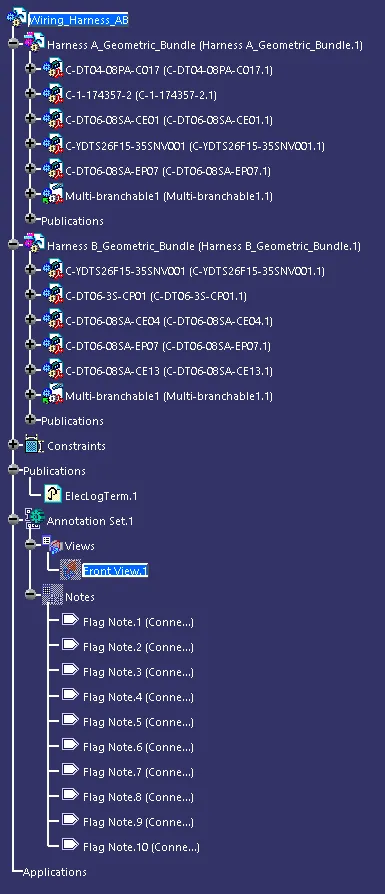
- Add annotation to all connectors. Make assumptions for annotations like connect 1, 2, etc.
- Check for the bundle warning. Add snap.
- Generate CAT.part of harness assembly and convert is in. igs format.
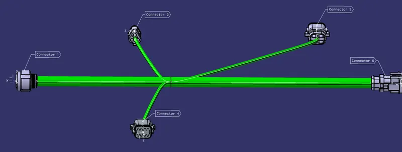
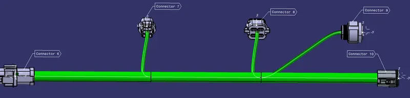
GIVEN LAYOUT:
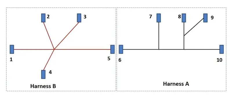
GIVEN CONNECTORS:
Harness B:
1_YDTS26F15-35SNV001
2_DT06-3S-CP01
3_DT06-08SA-CE04
4_DT06-08SA-EP07
5_DT06-08SA-CE13
Harness A:
6_DT04-08PA-C017
7_1-174357-2
8_DT06-08SA-CE01
9_YDTS26F15-35SNV001
10_DT06-08SA-EP07
PROCESS:
1. Define all the connectors of Harness B and Harness A in the Electrical Part Design Workbench. Bundle Entry Point, Connector Connection Point and Connector Connection Axis (Y-Axis facing the other mating parts, and X-Axis facing the lock).
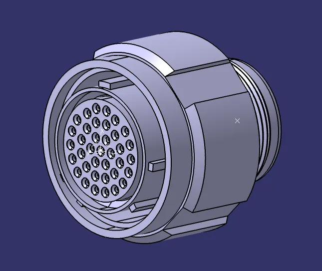
1_YDTS26F15-35SNV001
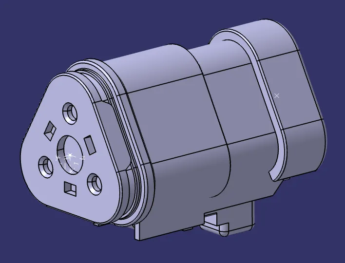
2_DT06-3S-CP01
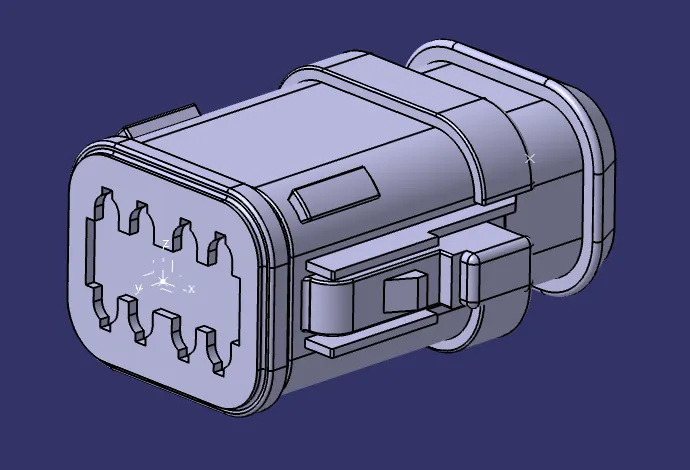
3_DT06-08SA-CE04
4_DT06-08SA-EP07
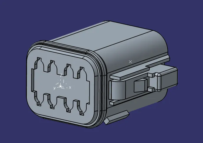
5_DT06-08SA-CE13
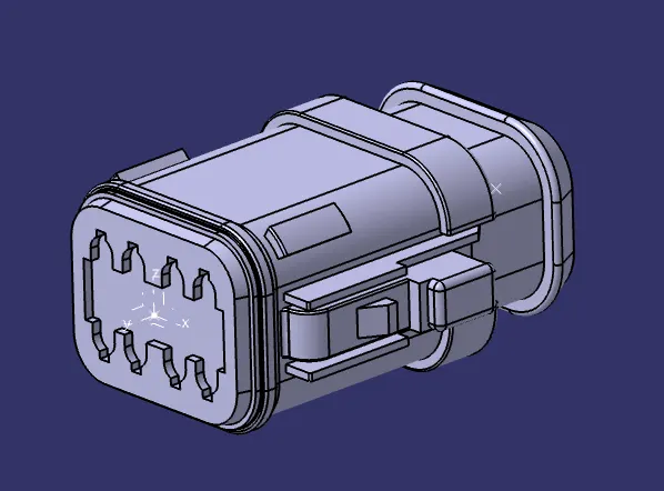
6_DT04-08PA-C017
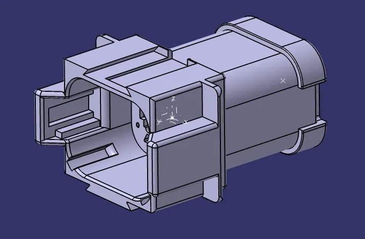
7_1-174357-2
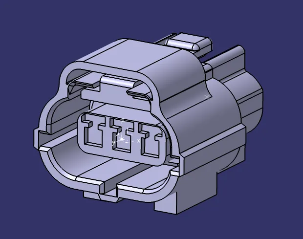
8_DT06-08SA-CE01
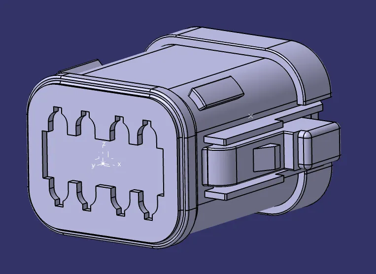
9_YDTS26F15-35SNV001
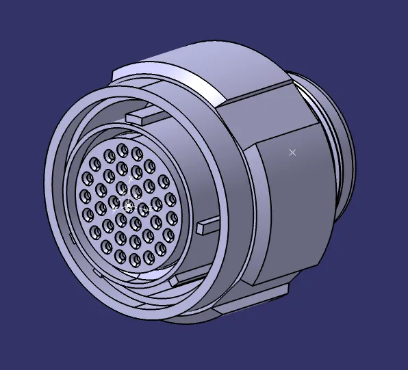
10_DT06-08SA-EP07
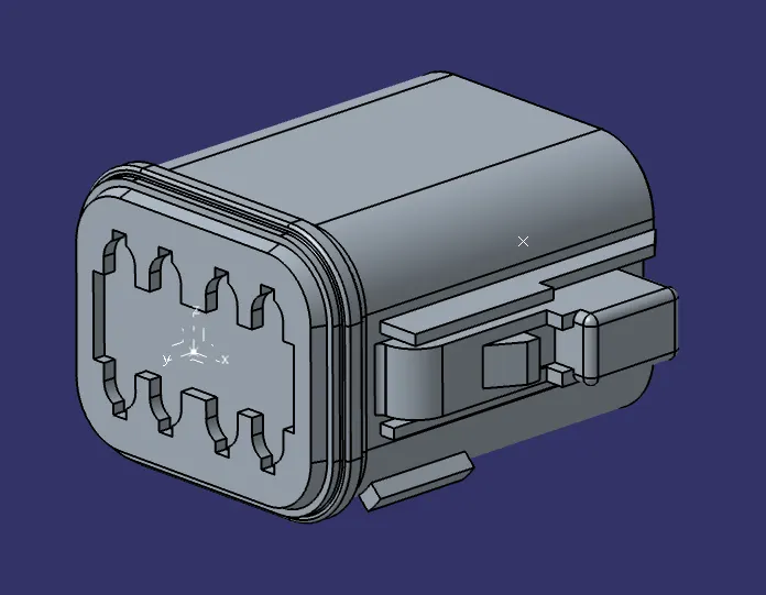
2. Insert Connectors from 1 to 5 in the product file and arrange them according to the Harness Layout B.
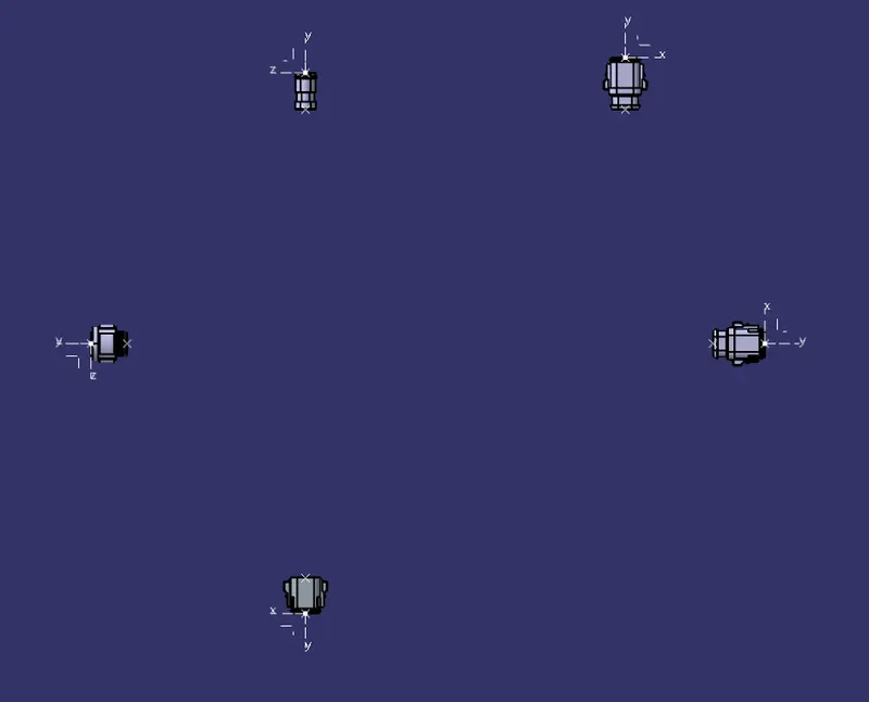
3. Switch to the Electrical Harness Assemble and define the product file as a geometrical bundle.
4. Connect the connectors 1 and 5 using Branch definition Command and add a Branch Point.

5. Using the same Branch point add Bundle Definition to the other connectors.
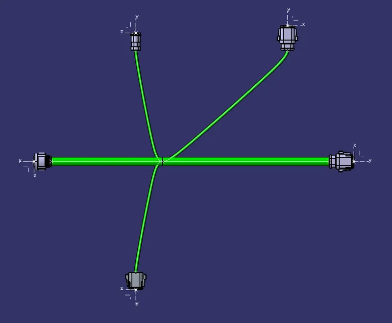
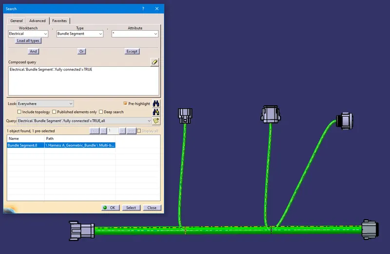
6. Using the Search Command check the bundle if it is fully connected.
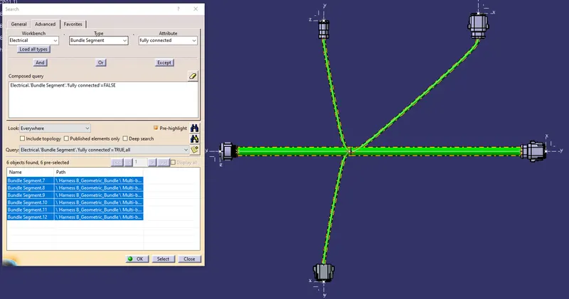
7. Repeat the same steps from 2 to 6 to create Harness A. insert Connectors in a product file and arrange them according to the Harness A Layout.
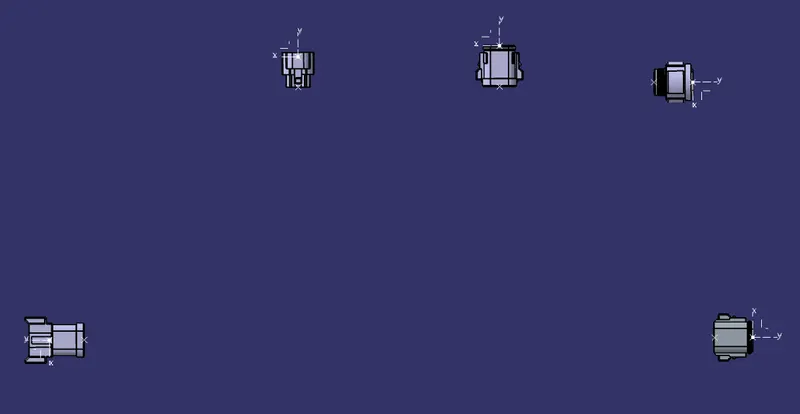
8. Switch to the Electrical Harness Assemble and define the product file as a geometrical bundle. Connect the connectors 6 and 10 using Branch definition Command and add Two Branch Point.
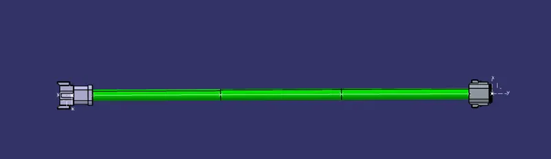
9. Using the First Branch point add Bundle Definition to connector 7 and Using the Second Branch point add Bundle Definition to connectors 8 & 9.
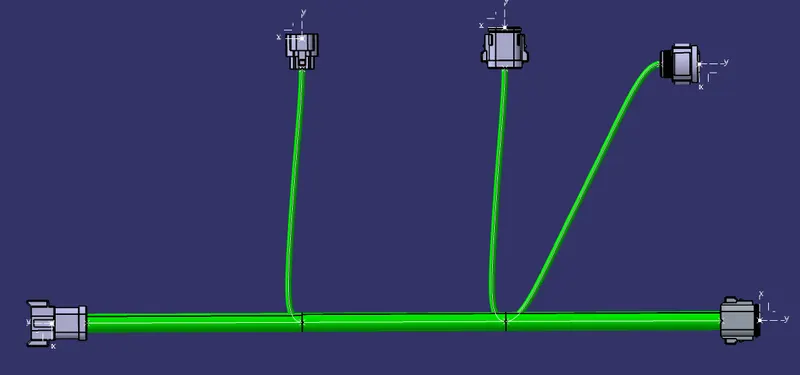
10. Using the Search Command check the bundle if it is fully connected.
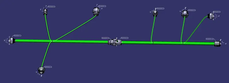
11. Create a New Product file and insert both Harness A and Harness B. Define the Product as Geometrical Bundle and connect connector 5 and connector 6 using Connect Electrical Devices in Electrical Harness Assembly Workbench.
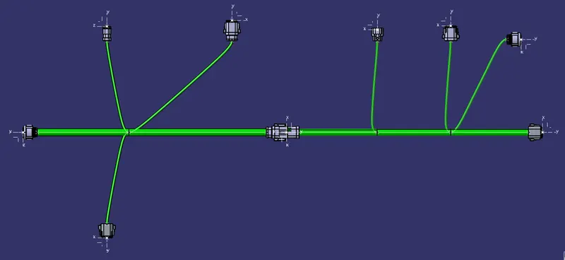
12. At last add annotation to all the connectors.