Wiring harness design in CATIA V5 - 3D modeling Week 5 & 6 Challenge
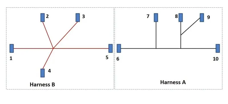
% Routing the following harness layout in electrical workbench.
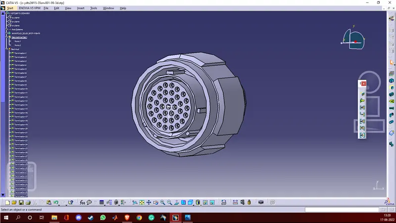
% Downloading and defining the connectors
- First we download the cad data from the link provided. After extracting all the files we have cad files of 10 connectors and layout diagrams.
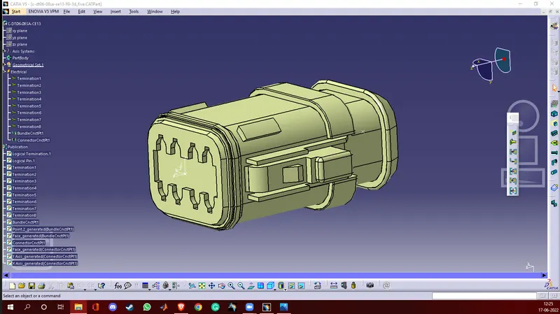
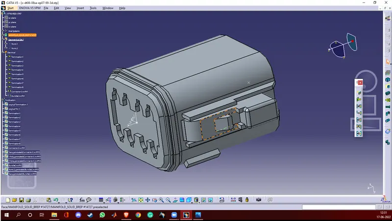
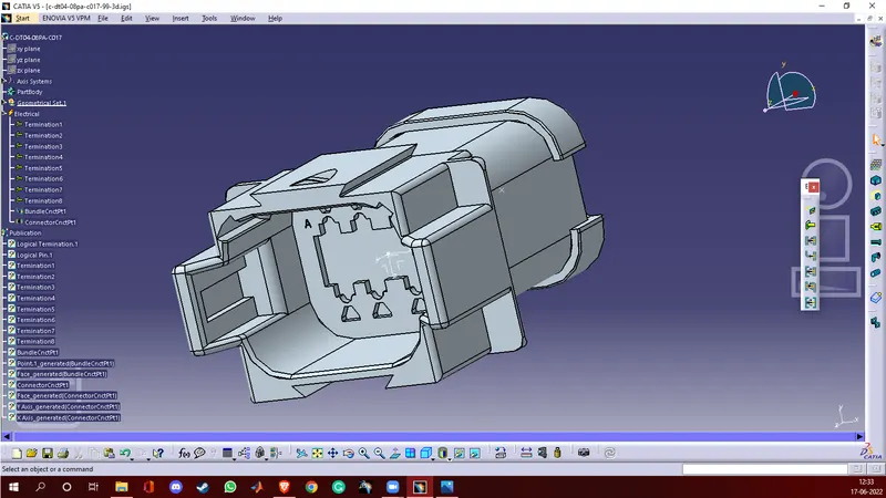
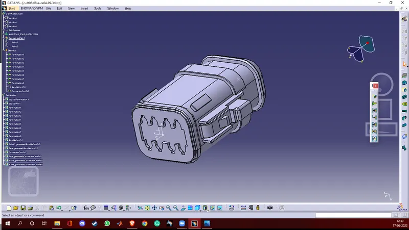
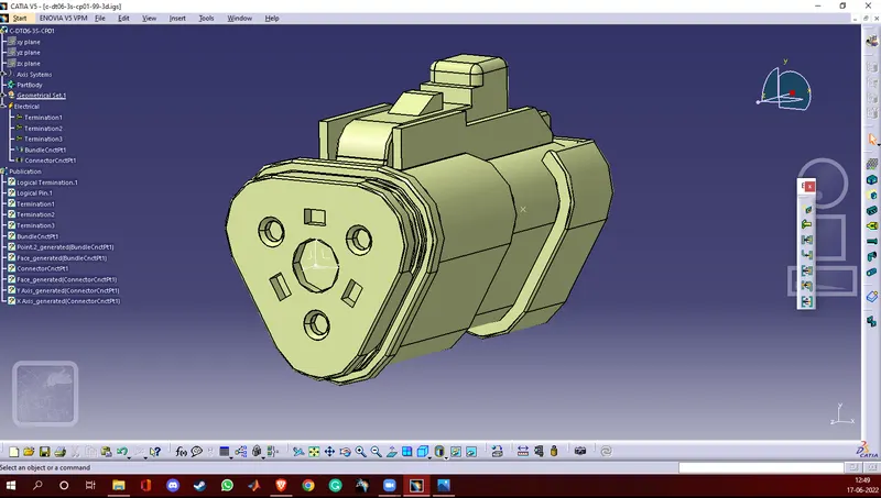
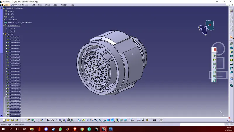
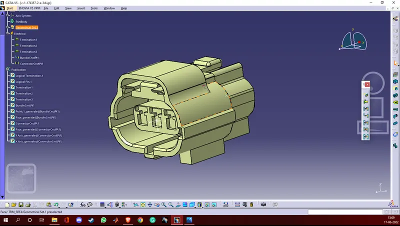
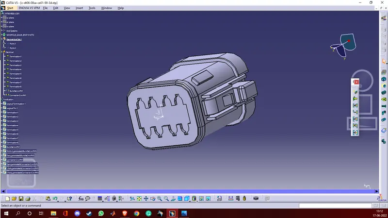
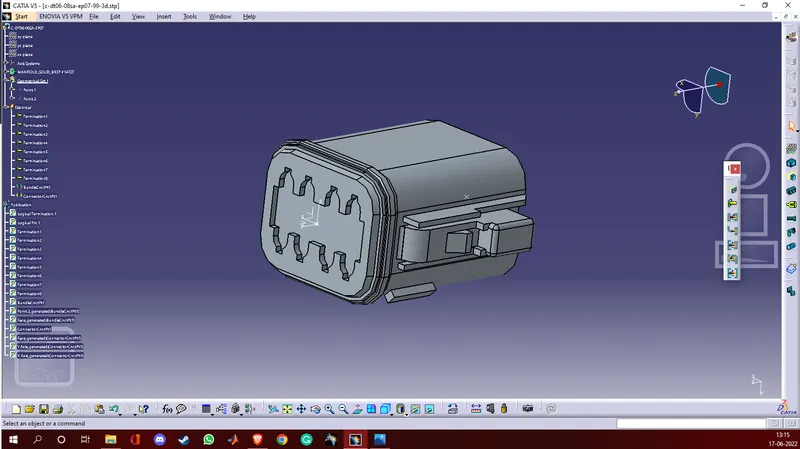
- Next in part design workbench, we add point and axis on the bundle connection point side and connector connection point side respectively on each connector separately.
- Now in the electric part design workbench we define each connector as an electrical connector. We define bundle connection point and connector connection point on each connector.
- Although we have 2 connectors common in Harness A and Harness B we will have to save them with different names or change their name later while connecting Harness A and Harness B.
% Screenshots
% Creating a catalogue
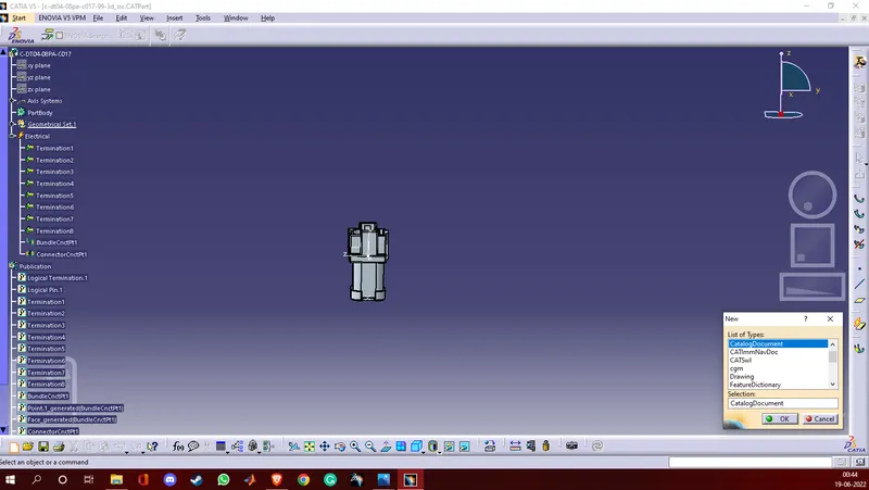
- First we create a catalogue by clicking on file>New part>Catalogue document.
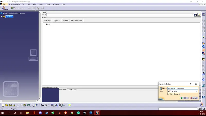
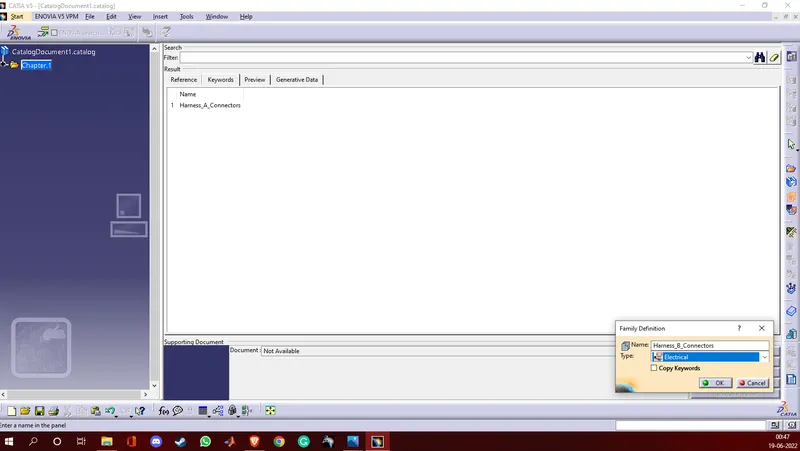
- While creating a catalogue we named the first family as Harness_A_connectors and the second family as Hrness_B_Connectors and selected the type as electrical for both the families and saved it.
- Next we added all the respective electrically defined connectors in the respective catalogue.
% Screenshots
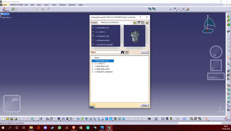
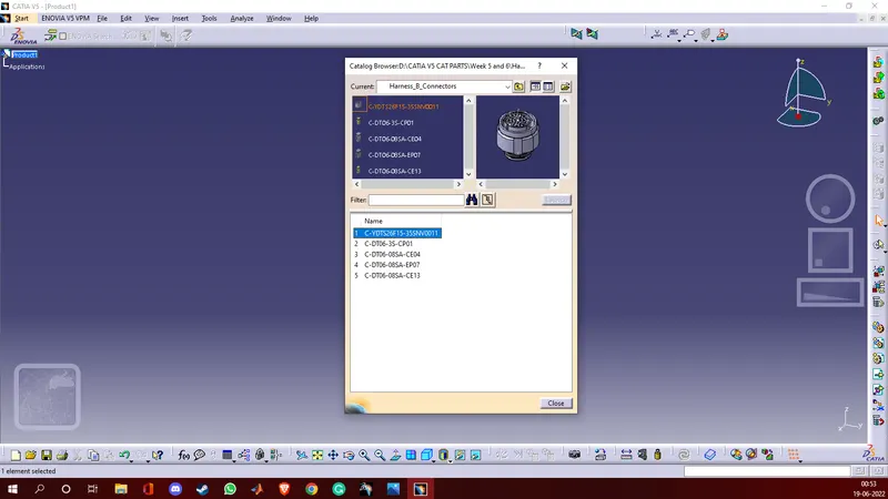
% Arranging the connectors as shown in the layout and creating bundle segments
- We arranged the connectors in the assembly design workbench. First, we added the required connectors to the assembly design workbench.
- Next using the compass manipulation and snap we arranged the connectors as shown in the layout.
- We made two assemblies Assembly A and Assembly B.
- Now we switch to electrical harness assembly workbench to create routings and branchable points.
- First we have to define the mechanical product as an electrical product to create bundle routings so we use the geometric bundle command and then select the product name on the tree structure.
- Now we can route the bundles and create branch points as we need.
% Screenshots
* Harness A
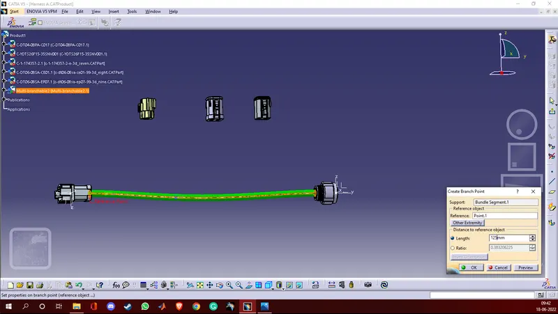
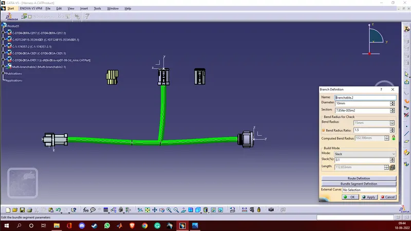
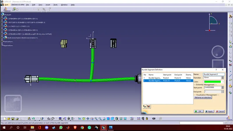
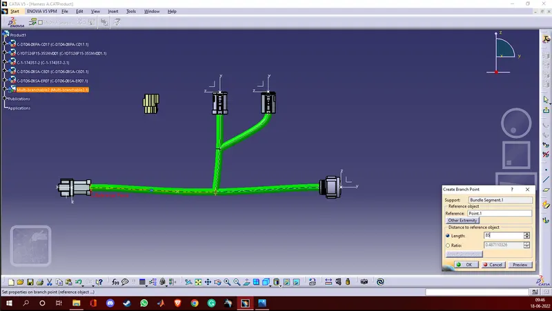
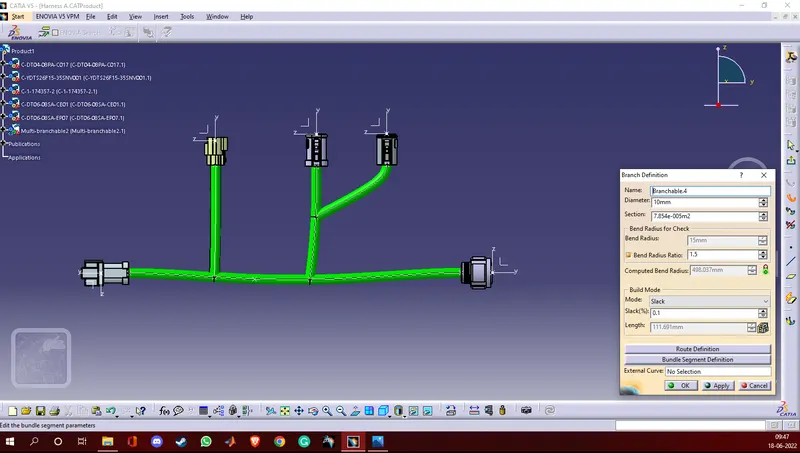
* Harness B
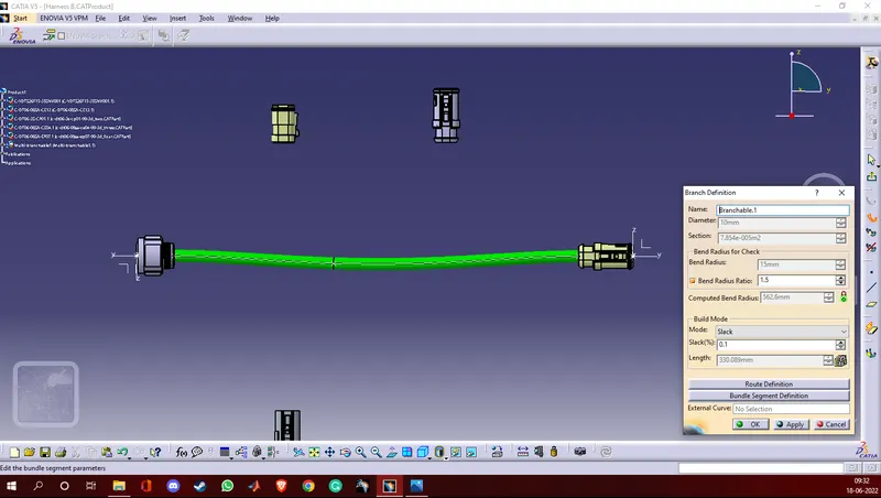
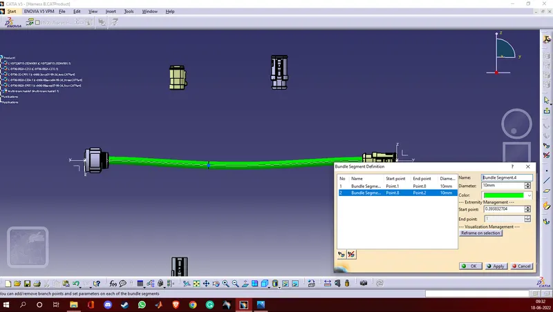
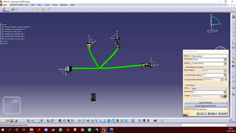
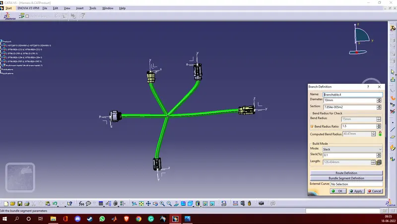
% Checking bundle continuity
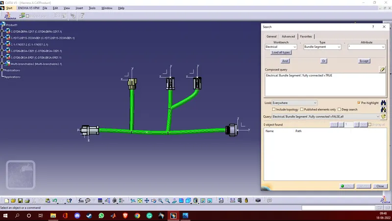
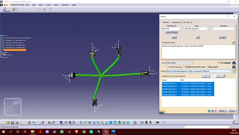
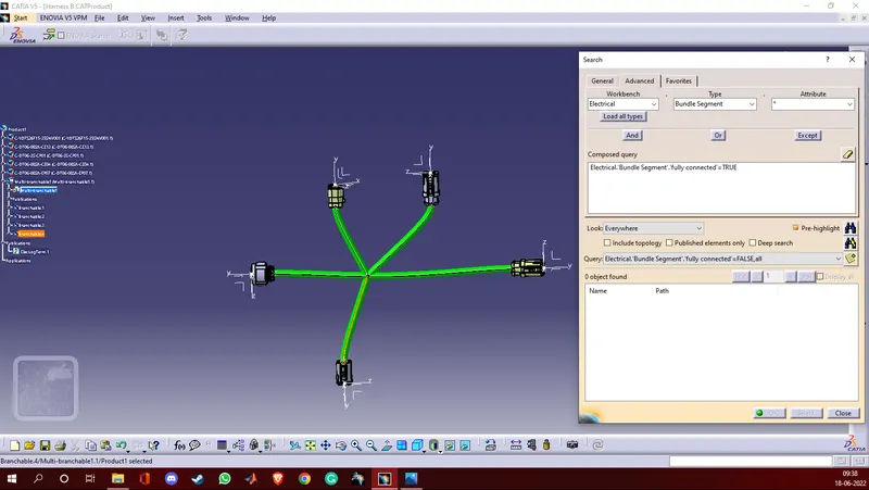
- Press ' ctrl+F ' > Search > Advanced. Select workbench as electrical, type bundle segment and attribute as fully connected.
- Select query as true to show all the connected bundle segments, and we can select false to show all the bundle segments which are not connected.
% Screenshots
* Harness A
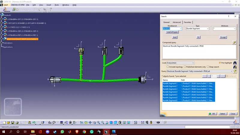
* Harness B
% Connecting Harness A and Harness B
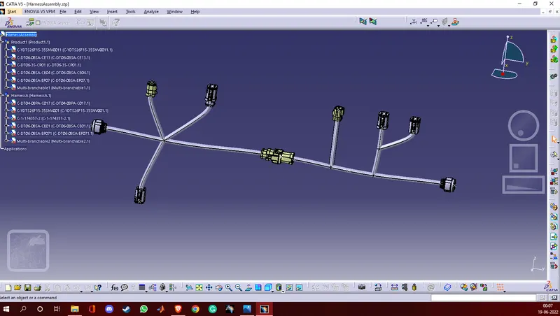
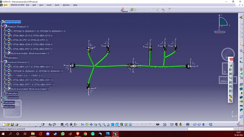
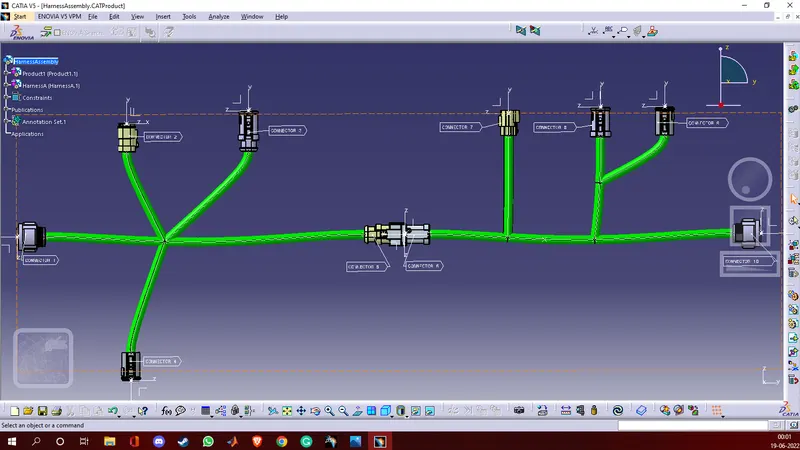
- A new product file named HarnessAssembly is created under electrical assembly design workbench. Harness A and Harness B are copied to this file.
- Using connect command the connectors 5 and 6 are connected electrically.
% Screenshot
% Adding Annotations
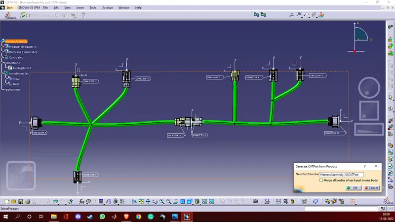
- A plane is selected for placing annotations using the command view creation in the electrical assembly design workbench.
- After selecting the front plane annotations are placed using the flag note with leader command.
% Screenshot
% Converting the product file to CATpart and saving it as .stp or .igs file format
- The product file is converted to CATpart in the mechanical assembly design using tools > generate CATPart from product.
- Select file > save as, save as .stp or .igs file.
% Screenshot