Wiring harness design in CATIA V5 - 3D modeling Week 4 Challenge
Report:
Objective:
- Route the following harness layout in Electrical workbench. Make assumption for harness bundle diameters. Use Following connectors as shown in layout diagram.
- Add protective covering on all branches connected to DT06-2S & DT06-4S connectors. Keep end extremity at 30mm (from connectors end).
Electrical Components:
- DT06-4S
- DT06-6S
- DT06-2S
- DT06-08SA
Harness Layout:
Design Methodology:
1.Download connector 3D data from www.te.com
- DT06-4S
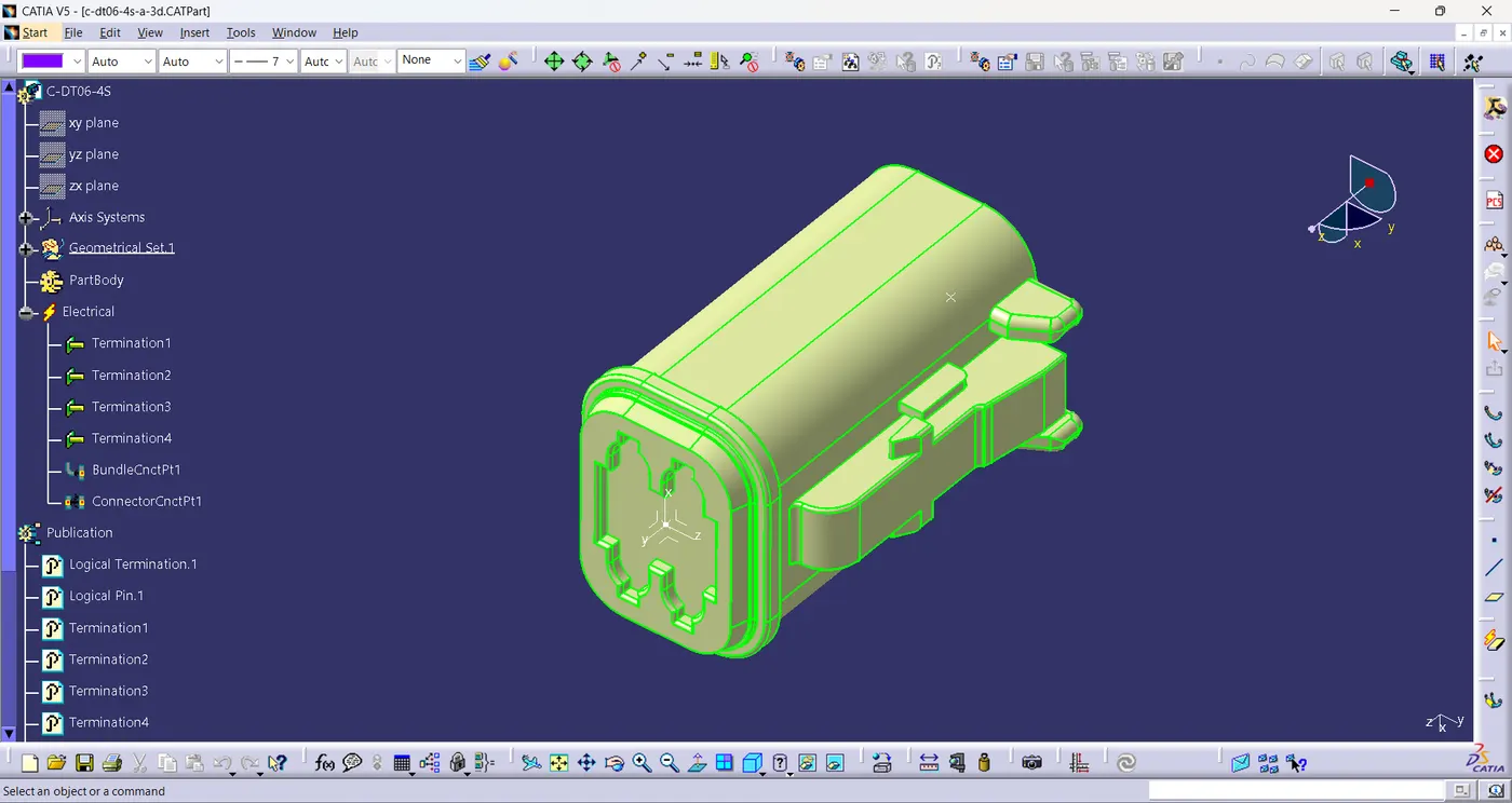
- DT06-6S
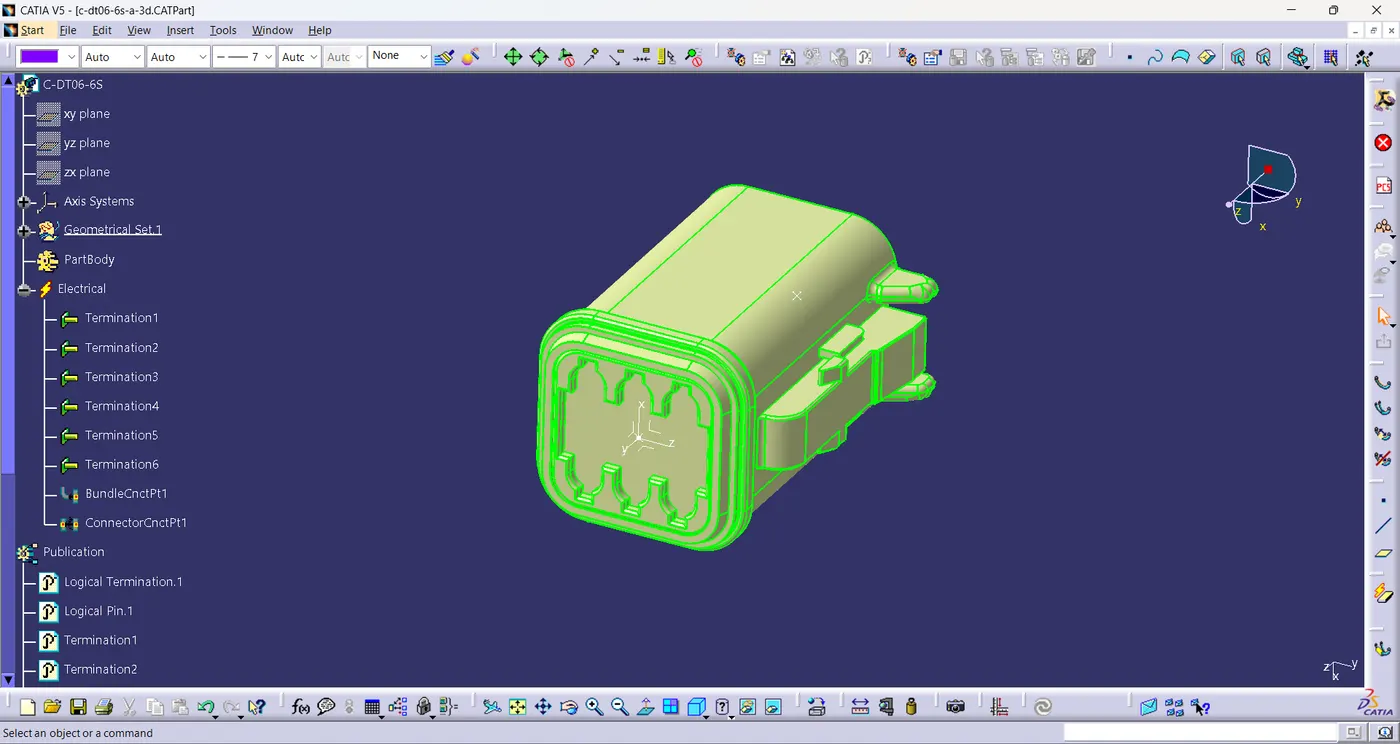
- DT06-2S
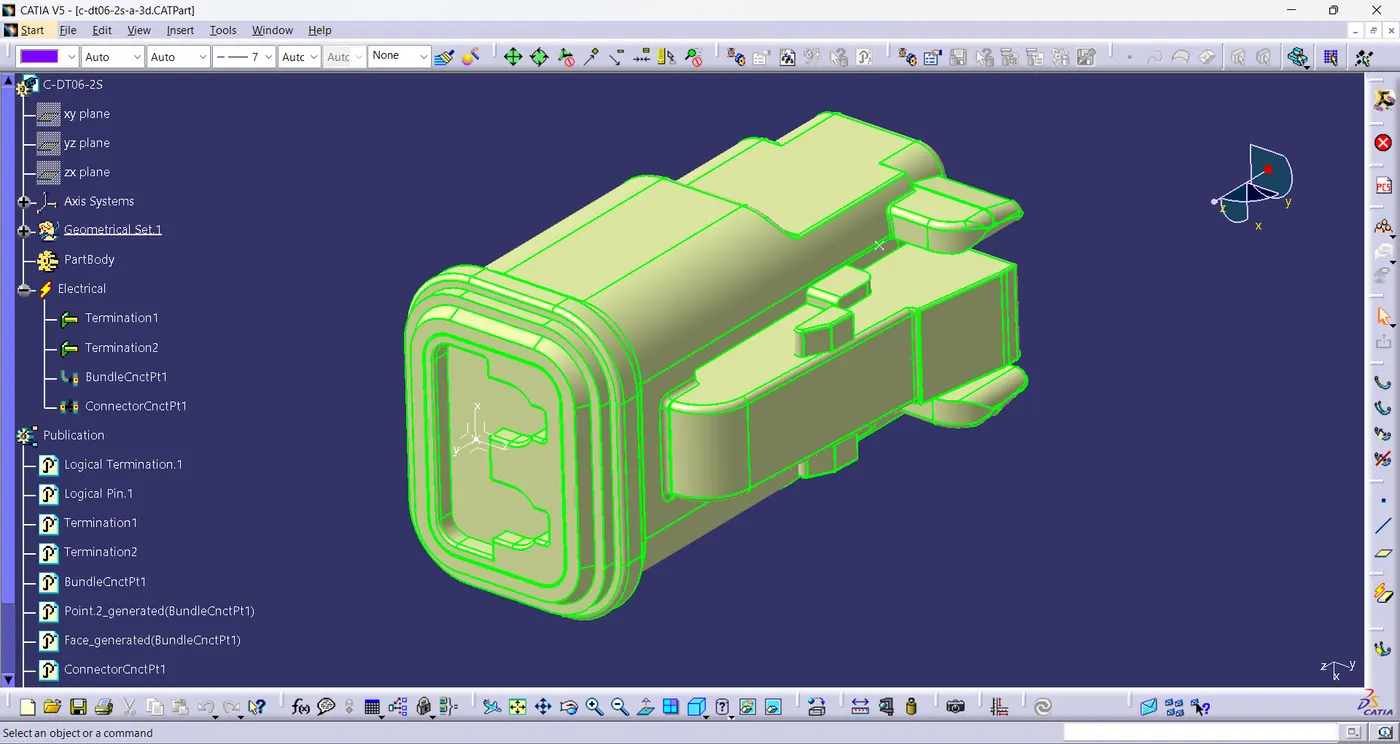
- DT06-08SA
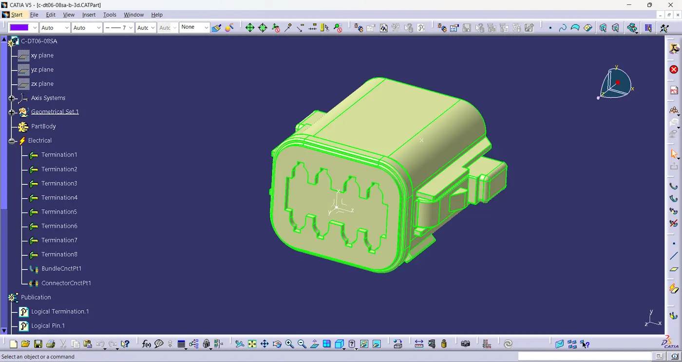
2.Define all the necessary electrical properties of the connectors by following the below steps and save it.
3.Create a product file and insert all the connector part file in it and arrange it .
4.metal plate is created as external reference for positioning the connectors.
5.connectors is arranged using the commands manipulation, compass/move, smart move, Translation/Rotation in the assembly workbench.
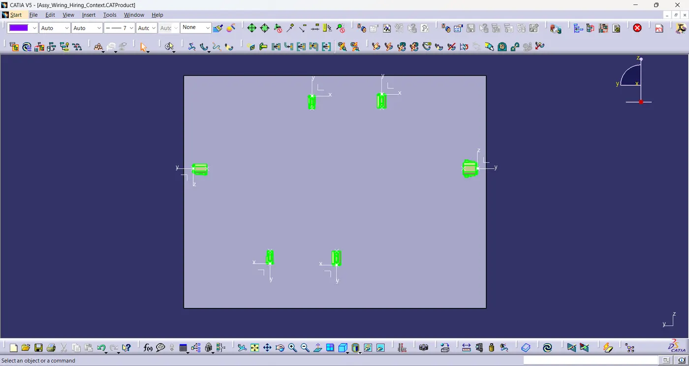
6.Layout is sketched on the metal plate as reference.
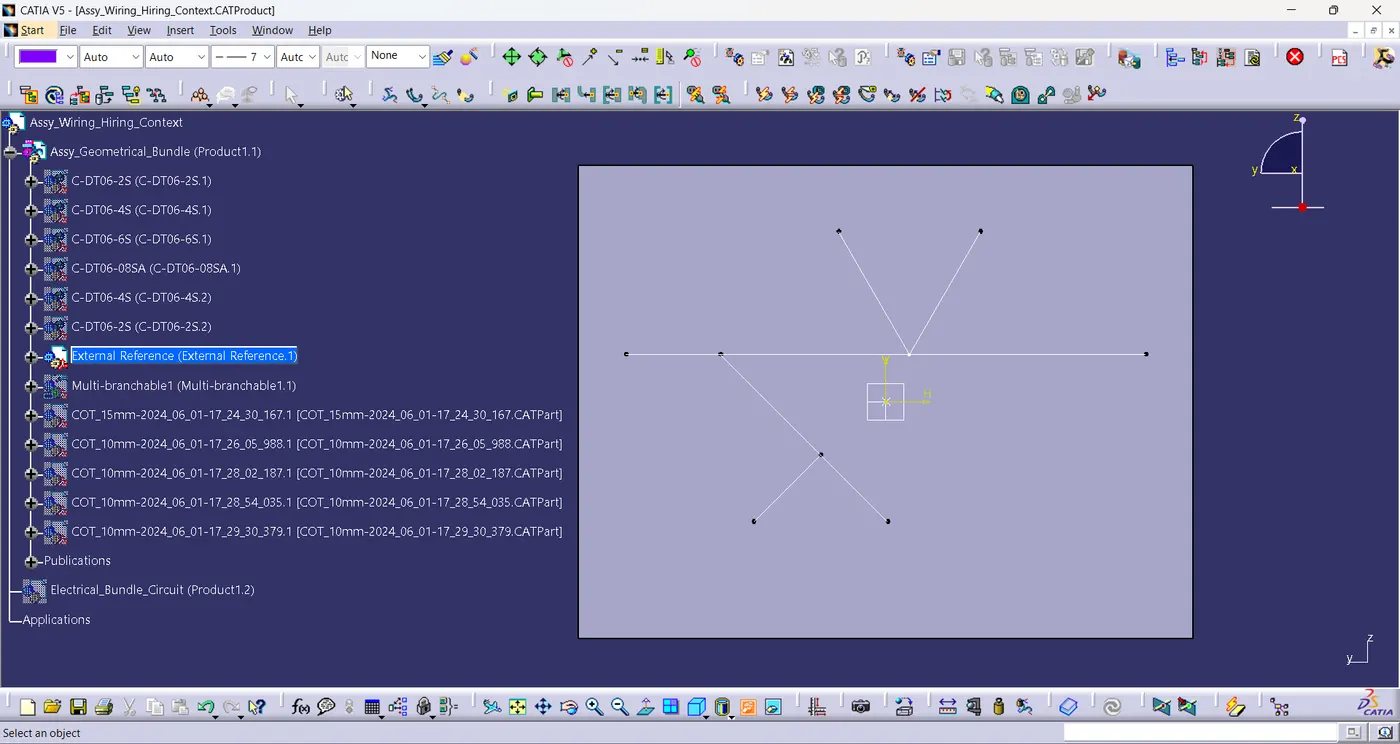
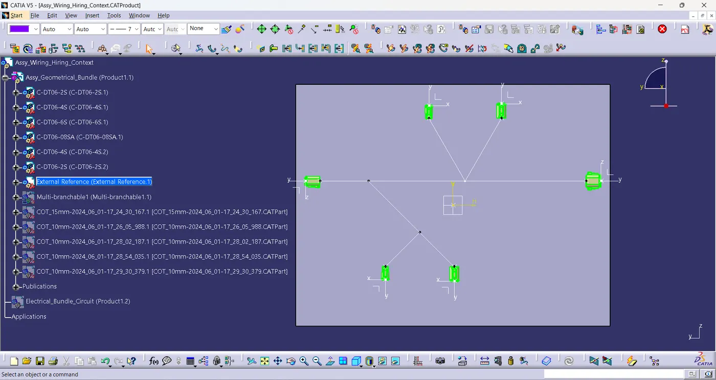
7.Multi-branchable command is used to create main branches.
8.Branch point command divides the branch to create the junction.
9.And branch definition command used to create the sub branches.
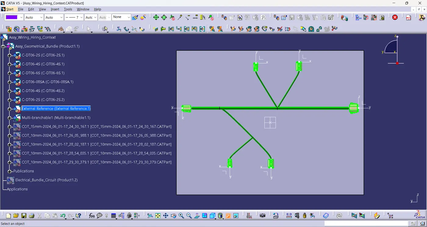
10.Protective covering command is used to create the cot tubes in the Catalogue document.
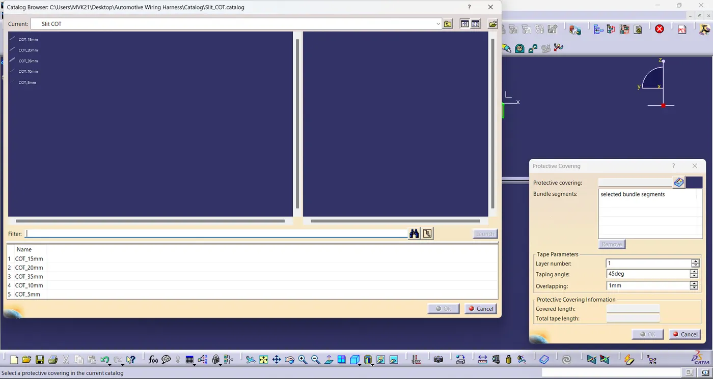
11.Corrugated tubes are added on the branches for the protection.
12.End extremity is provided 30mm from the cot tube end to connector end.
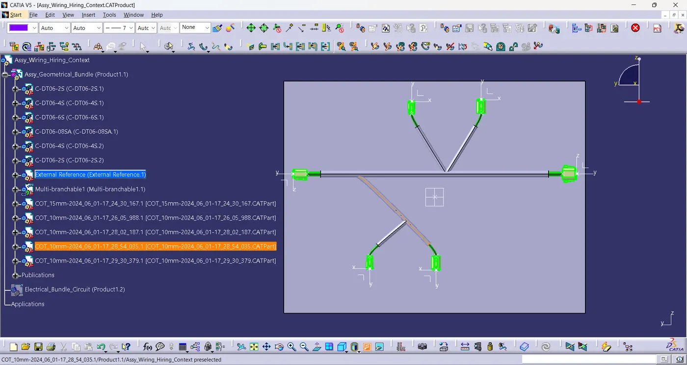
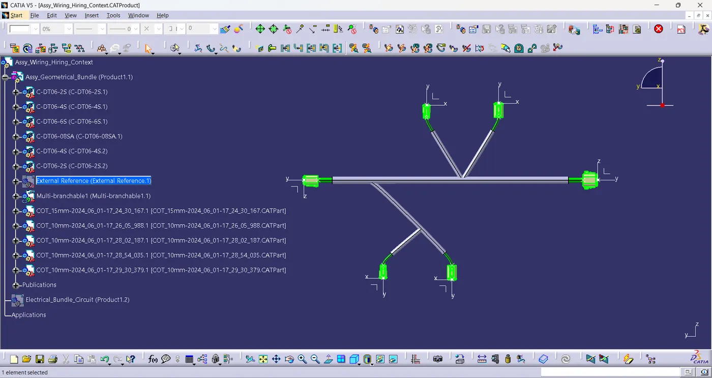
13.After completing the harness assembly hide then external references.
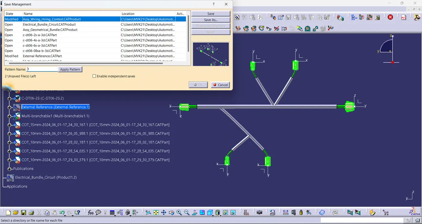
14.Save the assembly geometrical bundle using save management command.
15.Now save the Assembly context file.
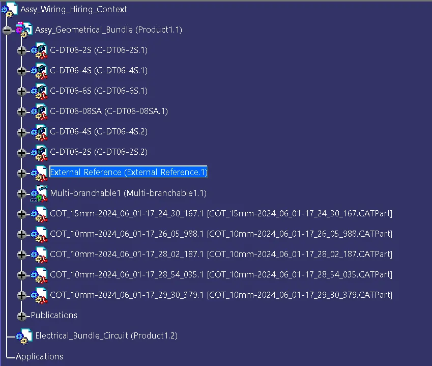
Graph Tree:
Conclusion:
- Harness layout is routed using electrical workbench.
- Protective coverings are added on the all branches.
- End extremity of 30mm is provided from the connector end to cot tubes end .