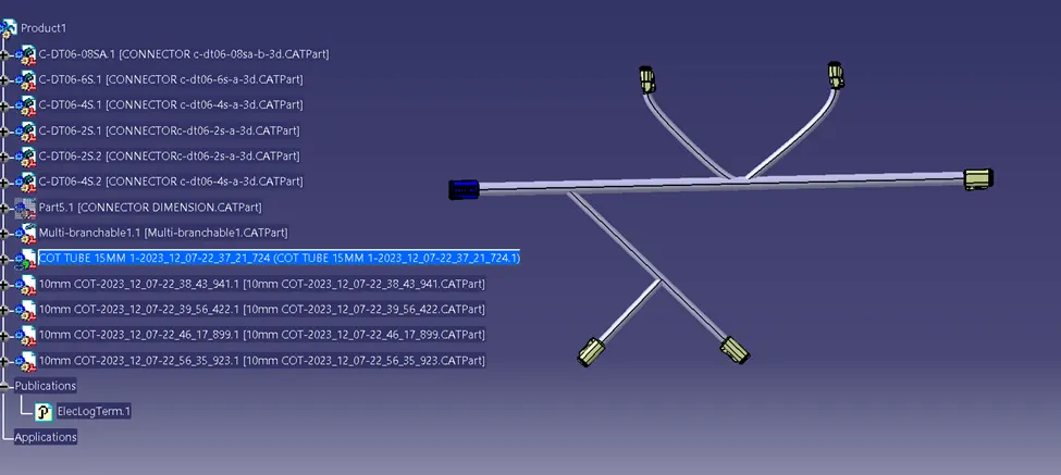
Wiring harness design in CATIA V5 - 3D modeling Week 4 Challenge
AIM-:
- DOWNLOAD ALL CONNECTOR FROM TE.COM.
- ELECTRICALLY DEFINE ALL CONNECTOR.
- CREATE MULTIPLE BRANCH BETWEEN ALL CONNECTOR.
1. DOWNLOADING THE FILE
- Go to the "CAD Files" then download the ".igs" file. (Which one is highlighted from yellow colour).
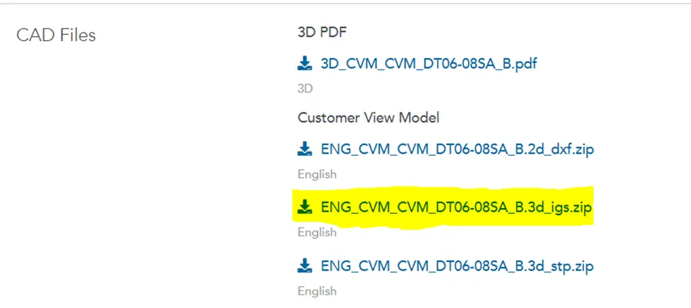
- Do the same to download all the files.
2. DEFINE CONNECTOR USING ELECTRIC PART DESIGN
- Open the download file in Catia.
- Go to the "Part Design" Work bench by clicking on "Start" then "Part Design".
- Create two point in middle portion for entry and exit point.
A) CONNECTOR (C-DT06-08SA)
(i) CREATE REQUIRED GEOMETRICAL PARAMETERS
- Create connector connection point and bundle connection point.
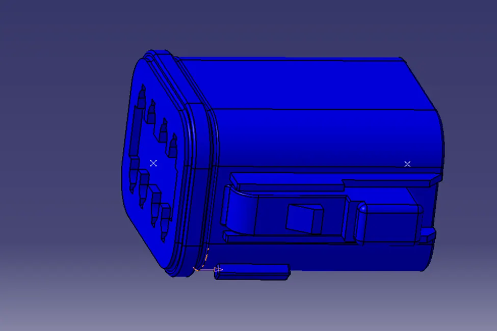
- Create the axis on Connector connection point.
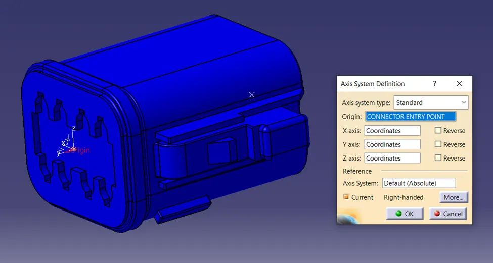
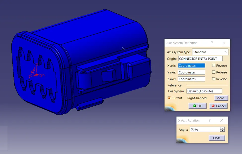
- The “Y axis” should be in the direction of mating face by right click on X axis and rotate by giving angle value.
- “X axis” on the horizontal direction and “Z axis” in the Top direction by right click on Y axis and rotate by giving angle value.
(ii) DEFINE PART AS CONNECTOR
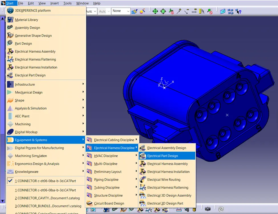
- Go to the “Start” then choose “Equipment & Systems” then choose “Electrical Harness Discipline” then choose “Electrical Part Design”.
- Go to the “Electrical Part Design” workbench.
- Go to the “Electrical Device Definition” then choose “Define Connector” option.
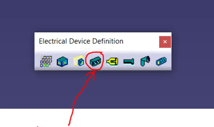
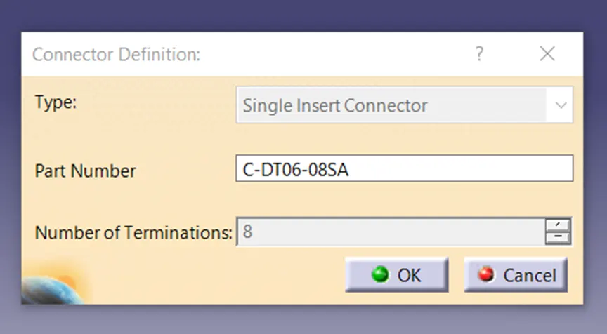
- Click on the body for Connector Definition box.
- In “Type” option choose “Single Insert Connector”
- For “Part Number” save name as it is.
- For “Number of Terminations”, Count the number of hole and put the value.
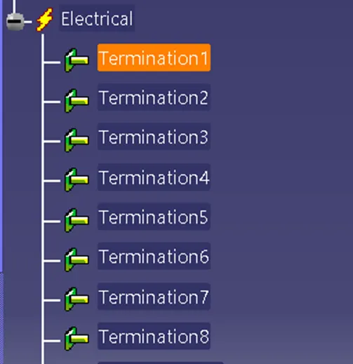
- Termination point is created on the feature tree.
- Can change the name or save it as it is.
(iii) DEFINE BUNDLE CONNECTION POINT
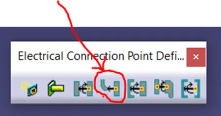
- Go to the “Electrical Connection Point Definition”.
- Choose “Define Bundle Connection Point”.
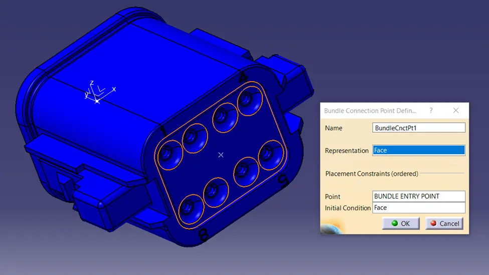
- Select the Connector body for Bundle connection point definition box.
- “Name” left it as it is or right the name here.
- Choose “Representation” option and choose the mating face of connector.
- Choose “Point” option and select the point from connector.
- Choose “Initial Condition” and select the mating face of connector again.
- Then click on ok.
(iv) DEFINE CONNECTOR CONNECTION POINT
- Go to the “Electrical Connection Point Definition”.
- Choose “Define Connector Connection Point”.
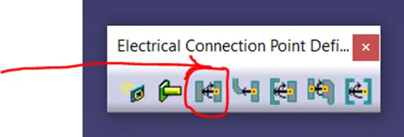
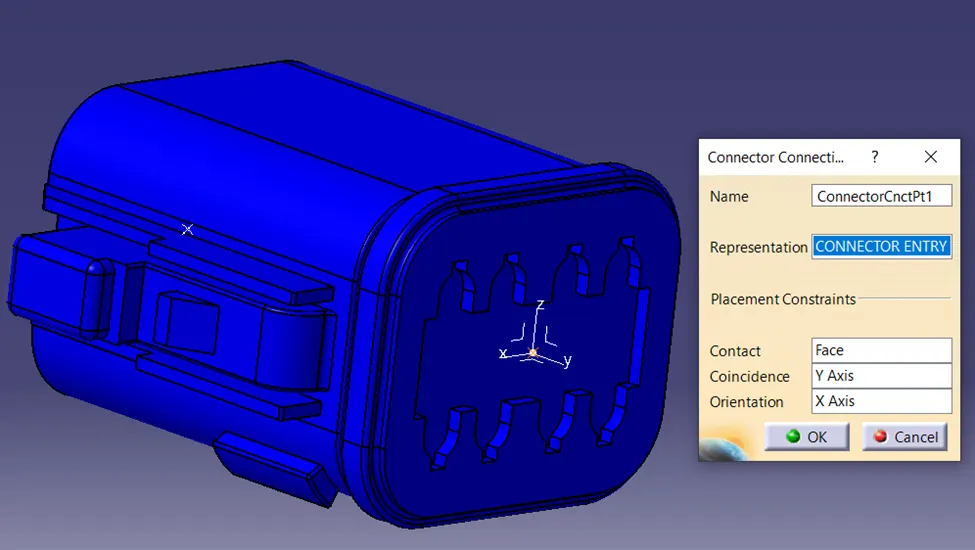
- Select the connector body for Connector Connection Definition box displayed.
- For “name” left it as it is.
- Choose “Representation” option then select the entry point of connector.
- Choose “Contact” option then click on the mating face of the connector.
- Choose “Coincidence” option and select the “Y axis”.
- Choose “Orientation” option and select the “X axis”.
- Click on ok.
- When the Electric Connector is define save the .Cat file.
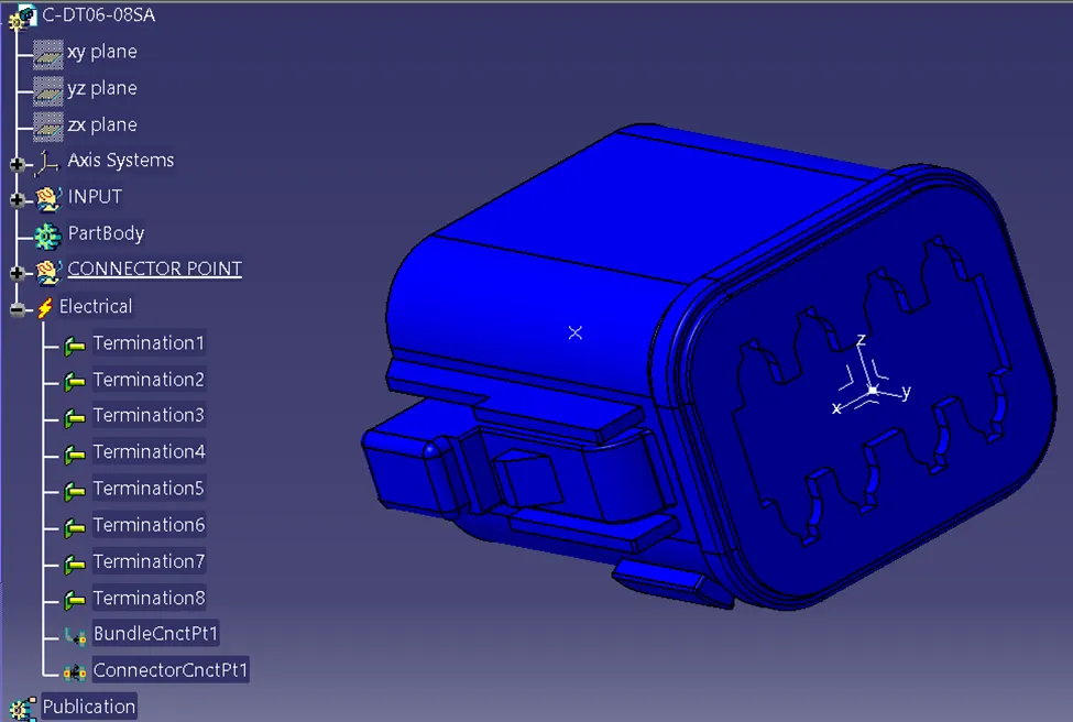
DEFINE ELECTRIC TO ALL CONNECTOR BY FOLLOW STEP (i) TO (iv).
3. CREATE SKETCH OF BRANCH WITH DIMENSION
- Go to the Mechanical part work bench.
- Select "Positioned Sketch", then select palne as "Reference" and "point" as Origin "Reference".
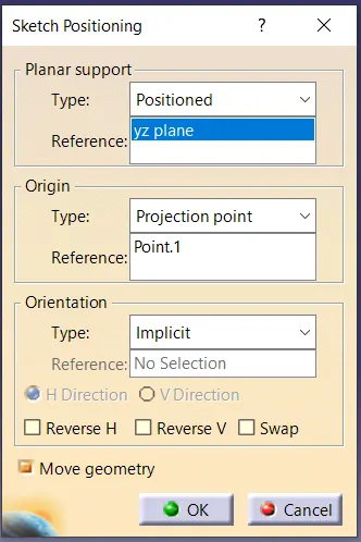
- Create sketch by follow given dimension in challenge.
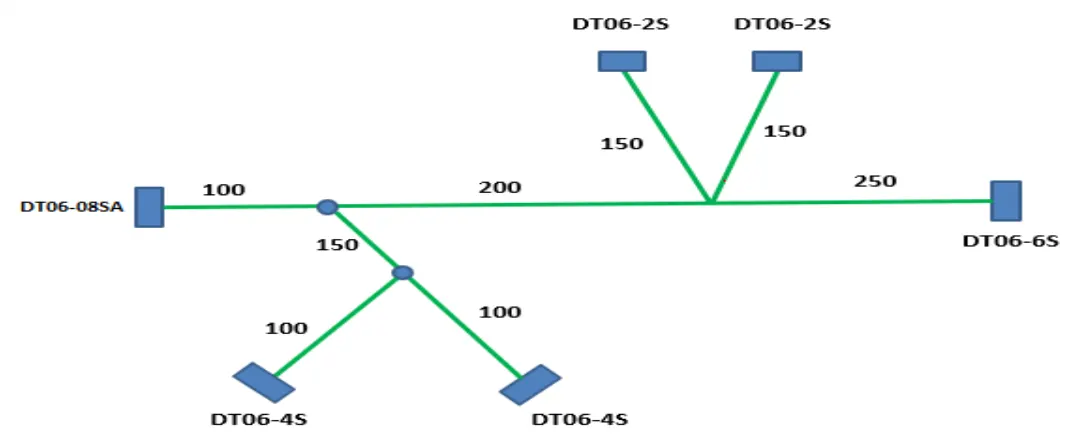
- Create sketch ith fully Constrained define.
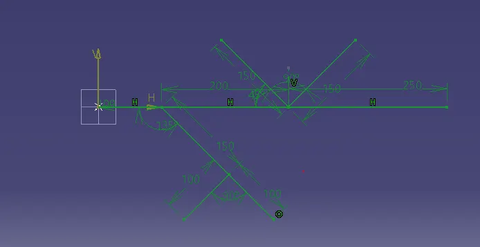
- Save the sketch.
4. CREATE BRANCH
- Go to the “Electrical Harness Assembly workbench.
- Copy and paste all connector here.
- Highlight “Product” from feature tree, then select “Geometrical Bundle” command then click on “Multi Branchable Document”.
- Click on “Branch Definition”, then “name” it and put the “Diameter” value and “Bend Radius Ratio” and “Slack (%)” value.
- Go to the Route Definition option.
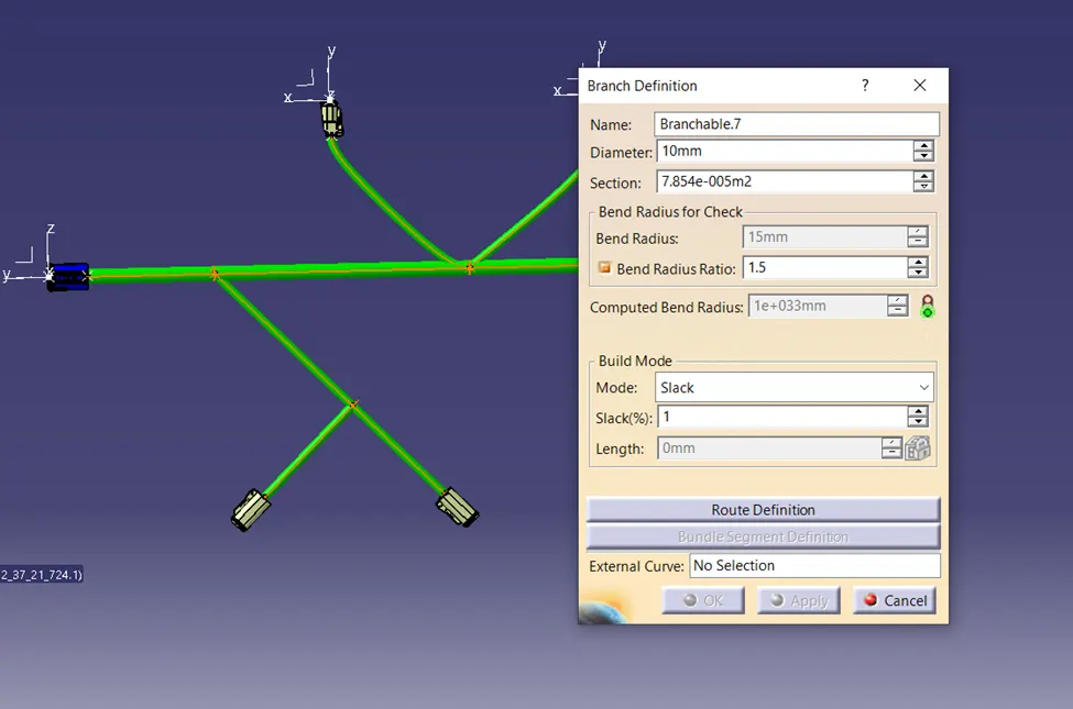
- Select first object then second object then click on ok.
- Give “Slack (%)” value according to smooth bend then click on ok.
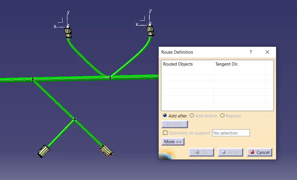
- Click on “add Branch Point” option.
- Select Branch then give the “Length” value, where Branch point is created then click on ok.
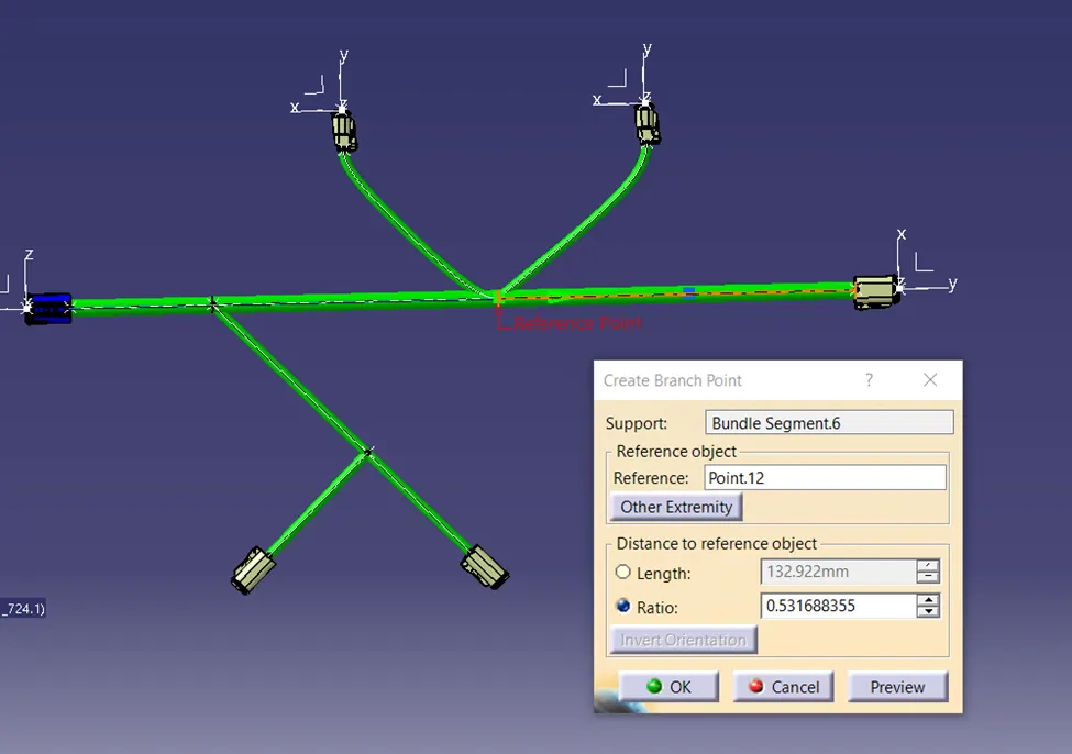
5. PROTECTION COVERING
- "Exit" from the Multiple Branch Definition display.
- Select "Protection Covering" option.
- Select Branch on “Bundle Segments”.
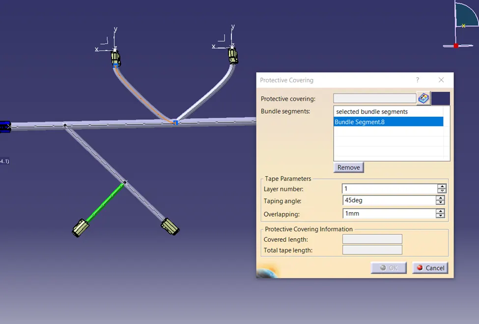
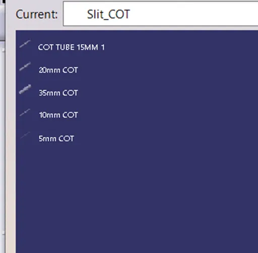
- GO TO THE “PROTECTIVE COVERING” ICON, SELECT CATALOG OF COT TUBE.
- SELECT COT TUBE.
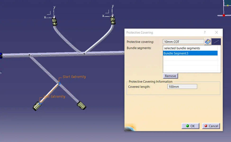
- Select Cot Tube End Extremity and give distance of 2mm. Then click on ok.
- By follow same procedure, create “Protection Covering” for all branches.
MAIN ASSEMBLY FILE NAME AS "CONNECTOR BRANCH 1".
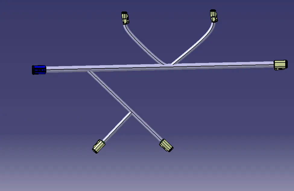
FINAL ASSEMBLY
FEATURE TREE