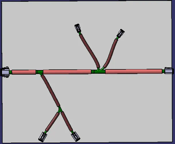
Wiring harness design in CATIA V5 - 3D modeling Week 4 Challenge
Downloading the given parts and Defining them as electrical component: (A single example is given and the same is followed for all other parts)
FOR DEFINING THE PART AS ELECTRICAL COMPONENTS:
Step - 1:
- Identify the Connector Side and the Bundle Side.
CONNECTOR SIDE:
BUNDLE SIDE:
Step - 2:
- create a mid-point on the bundle side in the Part Design Module to define the Bundle connection .
Step - 3:
- create a mid-point at the Connector side in the Part Design Module.
- create an axis system through the point.
- Define the axis as:
- X- axis - Towards Locking Mechanism of Clip
- Y- Axis - Front face of connector
- Z-Axis - Left or Right Direction of clip
Step - 4:
- Go to Electrical Part Design to define the Connector connection point and Bundle connection point.
Step - 5:
- First define the Connector and the number of Termination.
- Define the Bundle Connection Point.
- Define the Connector Connection Point.
DEFINING AS CONNECTOR:
DEFINING BUNDLE CONNECTION:
DEFINING CONNECTOR CONNECTION:
TREE STRUCTURE:
PREPARATION OF HARNESS ASSEMBLY:
Wiring harness product assembly contains
Harness context assembly:
Geometric bundle/Assembly and the wire harness electrical bundle.
Geometric Bundle:
Sub level product file containing harness components and physical bundle segments and braches.
Electrical Bundle:
Sub level product file contains all electrical circuit information.
- Create a assembly file.
- Add all the connector files inside this assembly
-
Then define this Geomteric bundle assembly as electrical assembly, by switching to Electric harness assembly workbench using Geometric bundle icon.
-
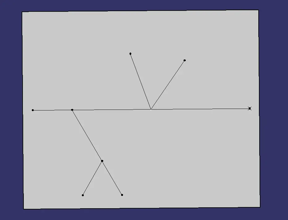
Create an environment using which you can assemble the components and create a sketch to position the components in the desired or provided dimensional locations.
- Positioning the imported components using Manipulation command
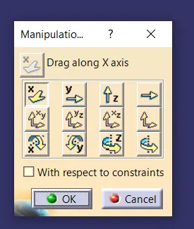 , snap command, Translation or raotation, smart move, Moving using the compass and edit option in compass to move or rotate.
 - By using the any one of the above mentioned command or their combinations to position the part .
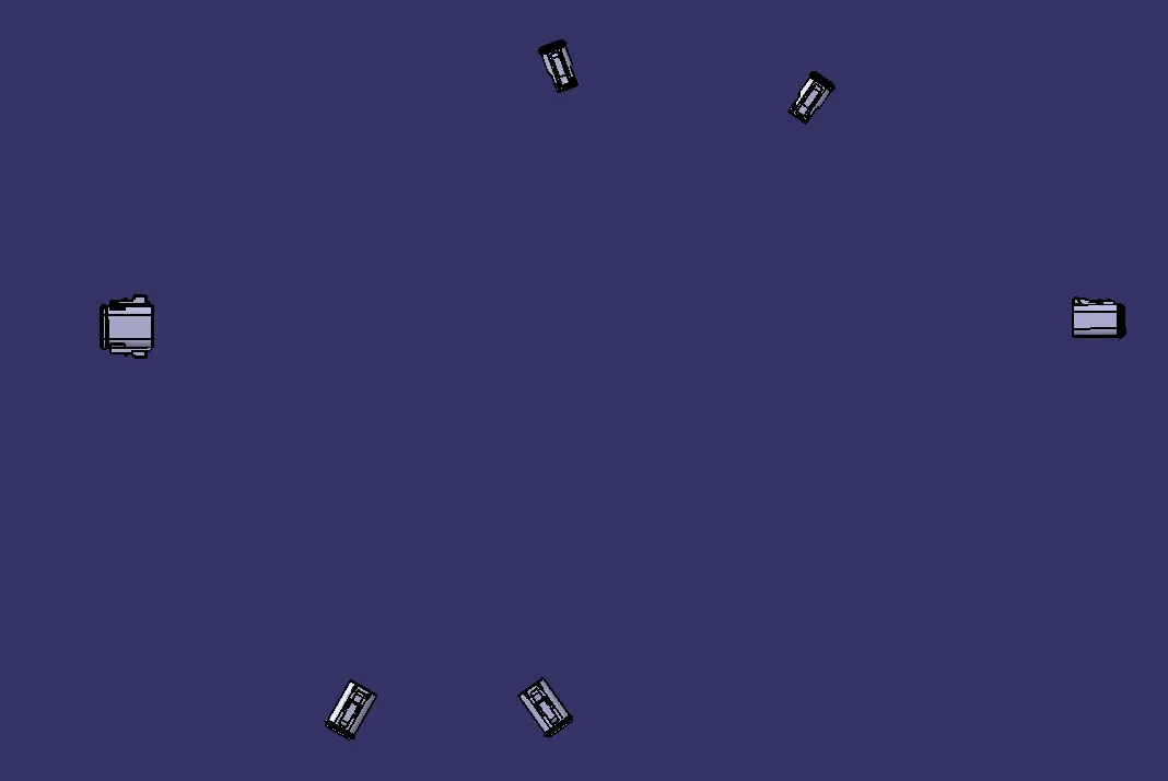
- Switch back to Electrical Harness Assembly
- Using Multi-branchable command
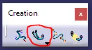 .
. 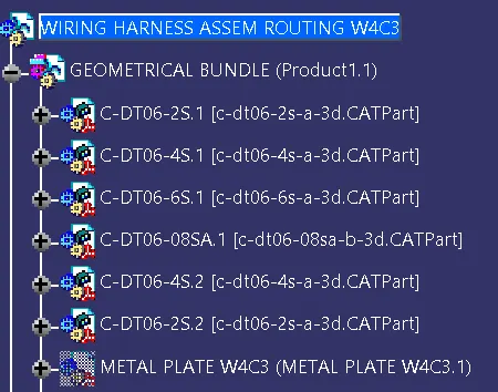 Now the routing can be done.
- In the Branch harness command
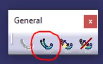
- Use route definition adding the initial connector and the next connector for routing.
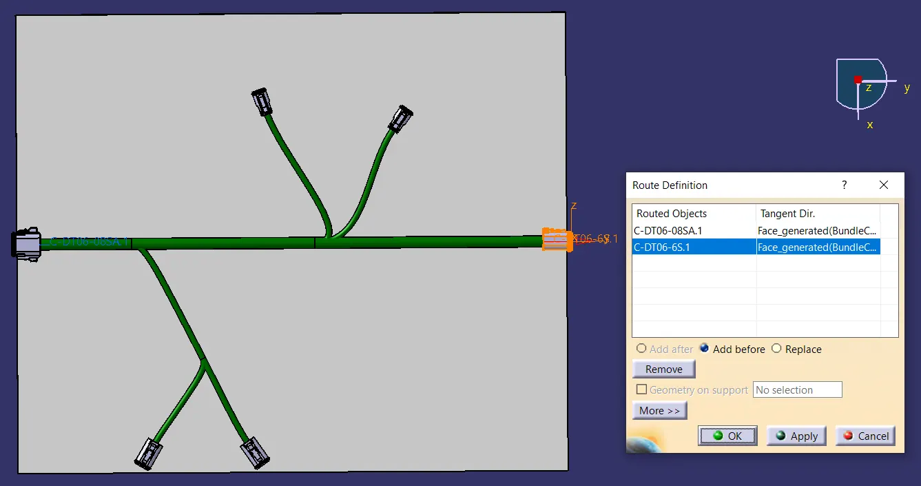
- To create a brach point.
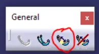
- To add protective covering
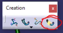 . You can use the tube added in the catalogue.
FINAL BRANCH FILE: