Wiring harness design in CATIA V5 - 3D modeling Week 4 Challenge
PREPARING THE BUNDLE ROUTING FOR THE CONNECTORS AND ORIENTING THE BUNDLE IN PROPER DIRECTION USING ROTATION TOOLS:
In this challenge we will define all the connectors as electrical part first and then we will create a aseembly for the connectors and we will define the assembly as an electrical assembly and then we will assemble all the connectors to the required place using the moving tools used in assembly work bench and then we will create the bundle routing to the connectors. and at the last we will use protective coverings (corrugated tubes) to the branches(bundle routing).
following are the components used in this challenge:
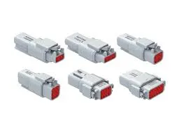
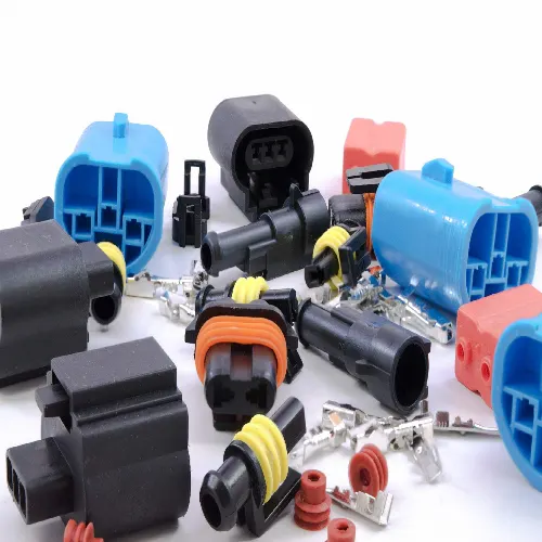
CONNECTORS: Automotive connectors are a component that very common for electronic engineering technician. Its function is very simple it sets up bridge of communication between the blocked or isolated circuits in the circuit, so that the current flows and the circuit realizes the predetermined function.
CORRUGATED TUBES:
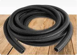
Corrugated tubes or pipes consist of plastic based insulating mateerial pipes with diameters varying in a corrugated shape. manufactured from a rigid material the pipes are dimensionally stable while the surface corrugation increases the products flexibility particularly in moving applications.
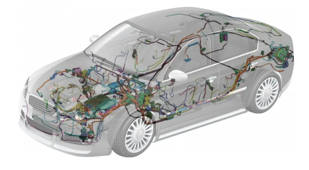
assembling the connectors and routing the wiring harness:
First we will download the connectors from TE.com website and then we will save them as a cat part and we will create two points one on the bundle entry side and other as the connector connection point and then we will define the connector as electric part using define connector command in the electrical part design workbench and then we will define the bundle entry point using bundle entry command and then we will define the connector connection point using connector connection point command and we will save the part as catpart. We will do the same for all the connectors so that all the coonectors are defined as elecrical part.
following are the coomands used to define the connector and the points electrically:
CONNECTOR CONNECTION POINT:

BUNDLE ENTRY POINT:

DEFINE CONNECTOR:

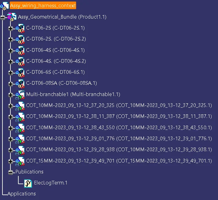
After defining all the connectors electrically we move to the assembly workbench and we will create a main product file in which we will store the sub assembly files for the main assembly product file we will name it as Assy_wiring_Harness_context. and then we will create a second level assembly product file inside the main assembly product file and we will name it as the Assy_geometrical_bundle so that we can create the geometrical bundles inside it.
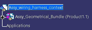
after creating the second level assembly file we will add the required connectors and other required things it using add component command and then define the assemblt file as electrical assembly file by using geometrical bundle command which is present in the electrical harness assembly workbench and then we will save it.
after that we will move the connectors as per our requirements using compass and other rotation tools such as manipulation, snap, smart move and we will recieve output as follows:
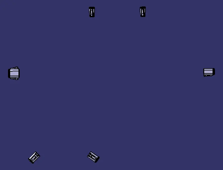
after placing the connectors to the required place we will create the wiring harness routing bundle using multi branchable document command to create the wiring harness routing. after selecting that command we will select the required connectors and then we will craete the routing bundle and then we have to create the sub branches from the main branch for that first we need to add branch point so that the sub branch will come that branch point for cfreating the branch point we will use branch point command and we will create the branch point on the main branch as per our requirment length. and then we will add the sub branches using the same multi branchable document command and we will select the branch point and the connectors and we will give the direction as per our requirements byt his way we will create the sub branches for all the sub connectors and then we will recieve the output as follows:
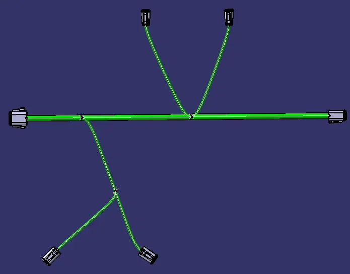
after creating the branches we have to add corrugated tubes to the branches so that it will be shock resistence for that we have to add corrugated tubes using protective covering command and then we have to select the required dia corrugated tube and then we have to add it to the branches.
but before adding the corrugated tubes the corrugated tubes has to be created by using define protection covering part command which is present in the electrical part design workbench and it has to stored in a catalogue by then only we can add the corrugated tubes to the barnches
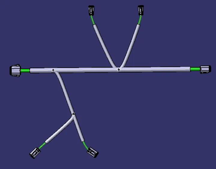
while adding the corrugated tubes we have to give a gap of 30mm from the connector so that the wiring for the connector can be done .
once if we done upto this much our aseembly is ready and we will recieve the output as follows:
and our tree structure sholud look somewhat like the following image: