Wiring harness design in CATIA V5 - 3D modeling Week 4 Challenge
WIRING HARNESS ROUTING
Regarding the given challenge , I have downloaded the igs CAD files of the connectors from the given link. Then I have extraced the files and open it on the CATIA V5 and converted it into CATPart file and saved it.
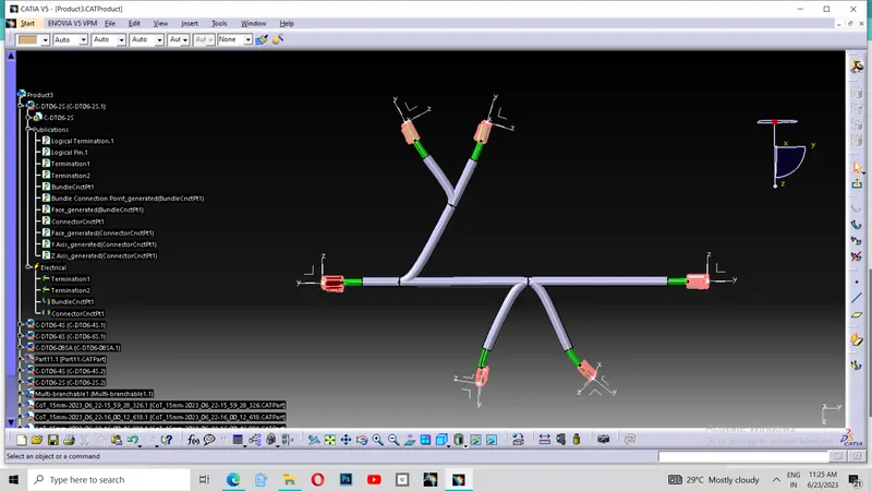
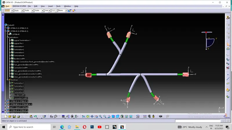
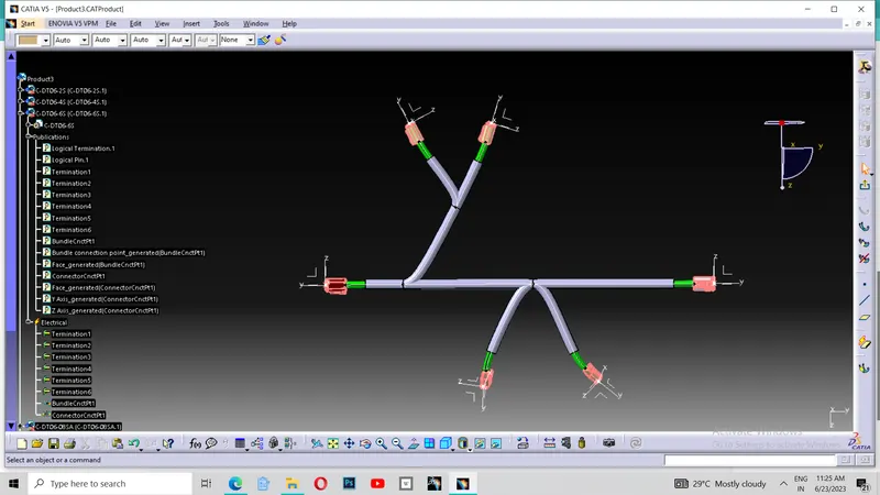
Then I started to define each of the components as per the steps required . That is, Importing CATPart files of the connectors, Create required geometrical parameters , Define part as Connector, Define "Bundle Connection Point", Define "Connector Connection Point" . Then I add them to the Catalogue.
Then I opened the new product file and inserted each defined connectors to the product file .Then copied needed quantity of the each component to the product file.
Then for the harness routing, there is a refernce in the challenge giving the position of the components and the distance of the harness route between the componets. As per the given diagram , I have drawn a sketch in the positioned sketch after creating a new part file.
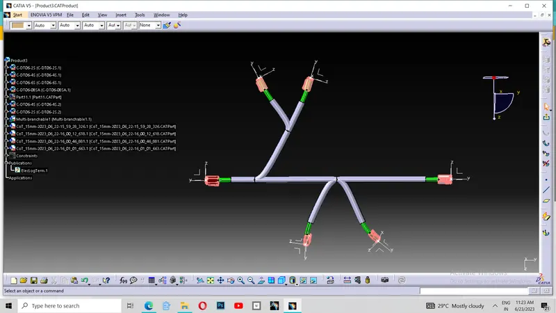
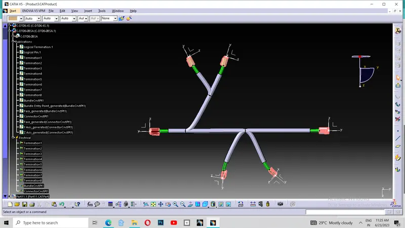
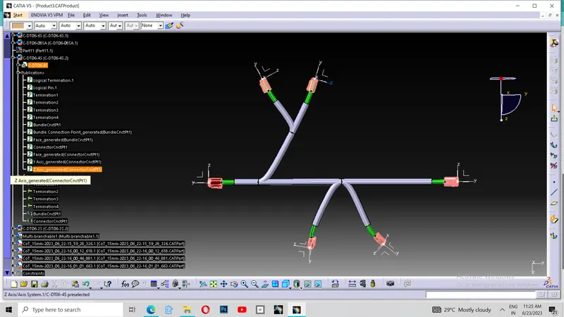
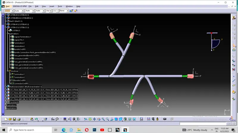
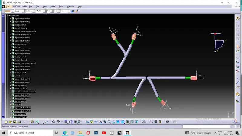
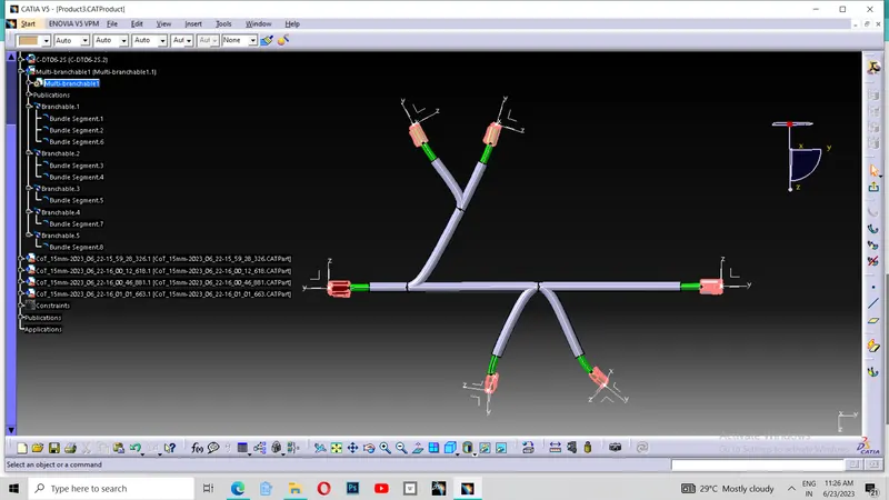
Then I started to defining the route of the harness with reference to the sketch I have drawn. Initially I have defined the route between C-DT06-6S and C-DT06-08SA with a dia of 10 mm and bend radius ratio of 1.5 using branch defintion tool in the Multibranchable document. Then I added Brach point using the tool named "Add Branch Point". Then I added points with reuired ratio. Then I defined the route between the a branch point and C-DT06-4S with dia of 10 mm and bend radius ratio of 1.5. Then I added the branch point to this branch with the required ratio and defined the route of the harness from the branch point to another C-DT06-4S with 10 mm of dia and 1.5 of bend radius ratio. Then from the other branch point in the main branch, I have defined the route of the harness to both C-DT06-2S 's from the same branch point seperately with 10 mm of dia and 1.5 of bend radius ratio.Then I exited from the Multibarnchable document. Thus I have done in the routing defintion.
Then I started to add Corrugated tubes to it. For that ,I used the tool named "protective covering" and browsed the corrugated tube Catalogue and added 15 mm dia CoT (which is greater that 10 mm) by keeping the end extremities at 30 mm from the components. Then I saved the file as Save management . Then zipped all the file together . Here I submitting my file. Thankyou.