Wiring harness design in CATIA V5 - 3D modeling Week 4 Challenge
WIRING HARNESS ASSEMBLY CHALLENGE-04
Aim: To create a wiring harness assembly using the provided electrical components and by following harness desig parameters using catia V 5 software
Procedure folowed:
The steps include are the
- Creating the Assy- wiring harness context product file
- Creating the geometrical bundle
- Adding the required background data in the context assy
- Define the wiring harness routing
- Creting the protective covering
- Save the assembly as the save managenment feature
Creating the Assy- wiring harness context product file:
First of all create a new product file and name it as the assy-wiring harness context product file and in the product file right click and click on the add new product and add another new product fil and name it as the geometric bundle
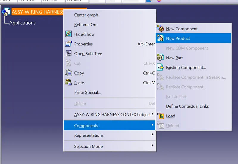
Name the product file as the geometric bundle
- Creating the geometrical bundle:
Now poen the new product file geometric bundle in the new window and add the electrical components including the connectors, clamps, clips etc
Before that download the connectors which are provided in the challenge from the wwe.TE.com
The connectoprs provided are the
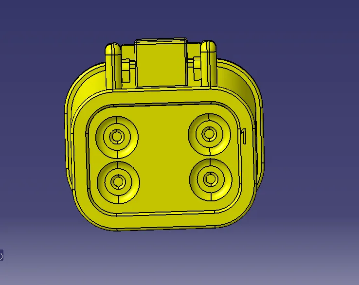
- DT06-4S
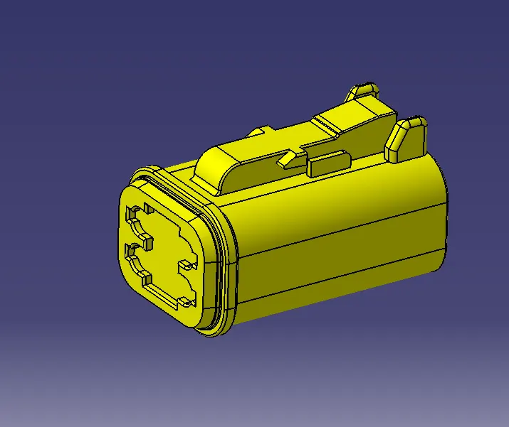
The mating connector side is
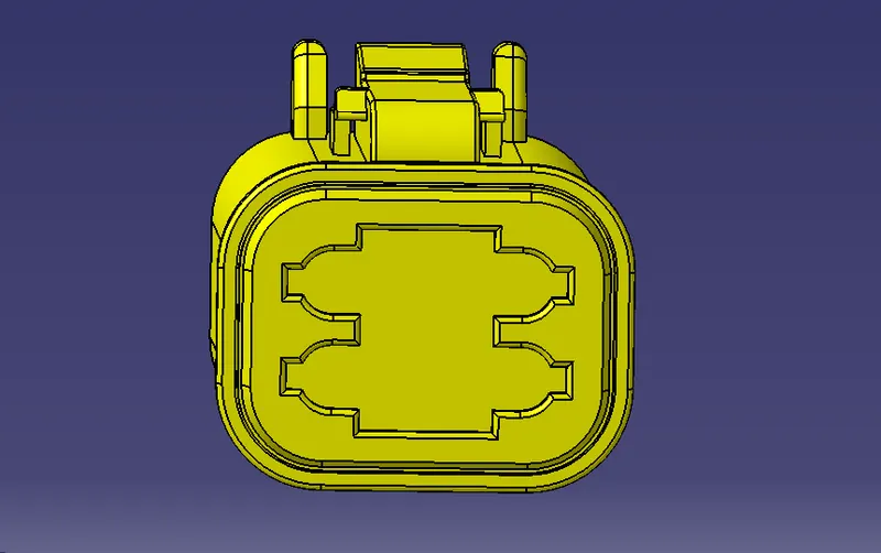
The bundle wire entry side is
Then define the given electrical component as the connector in the electrical part design workbench and then define electrical properties such as the connector connection point , bundle connection point, mating axis system etc
Connector connection point:
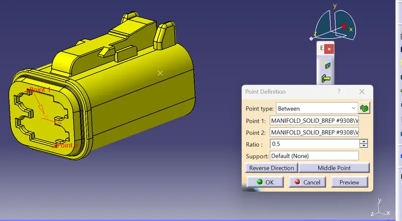
Bundle connection point:
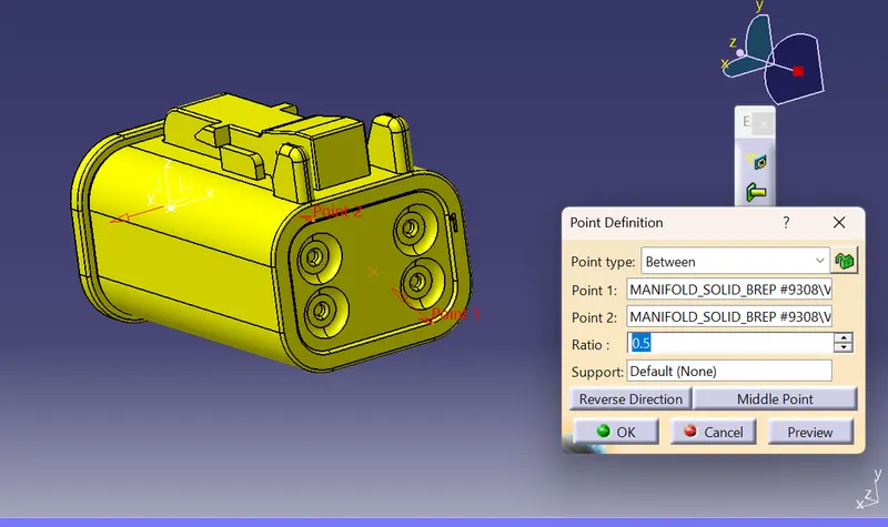
Mating axis system:
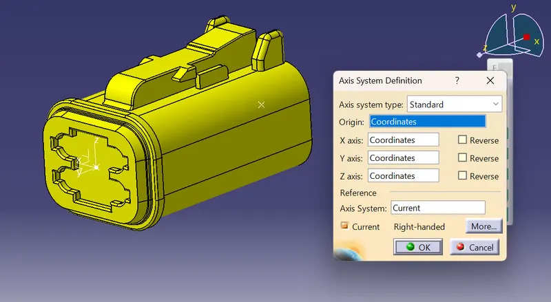
Now save the componemt
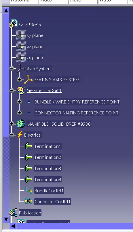
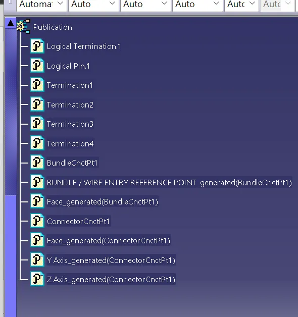
The tree structure is
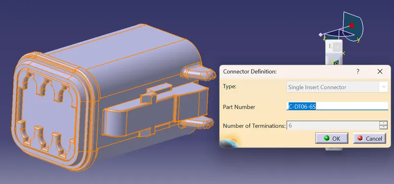
- DT06-6S
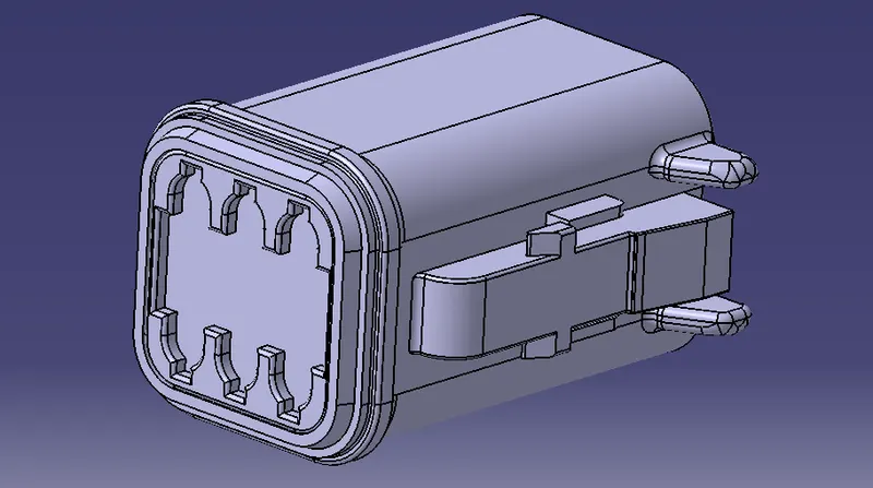
Define the componemt as the electrical by providing the number of terminations
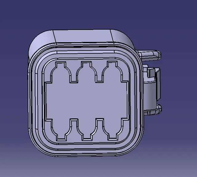
The mating connector side is
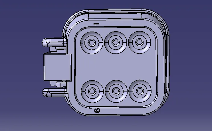
The bundle wire entry side is
Connector connection point:
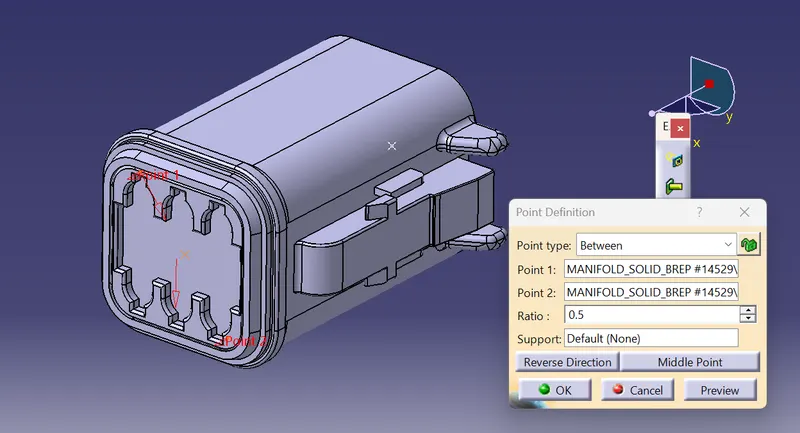
Bundle connection point:
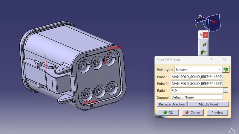
THe mating axis is
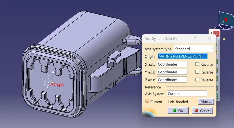
The tree structure is
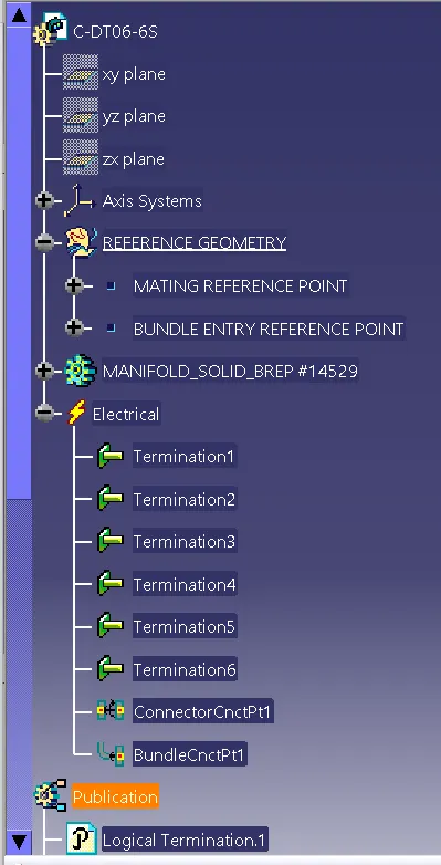
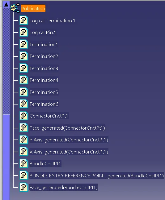
- DT06-2S
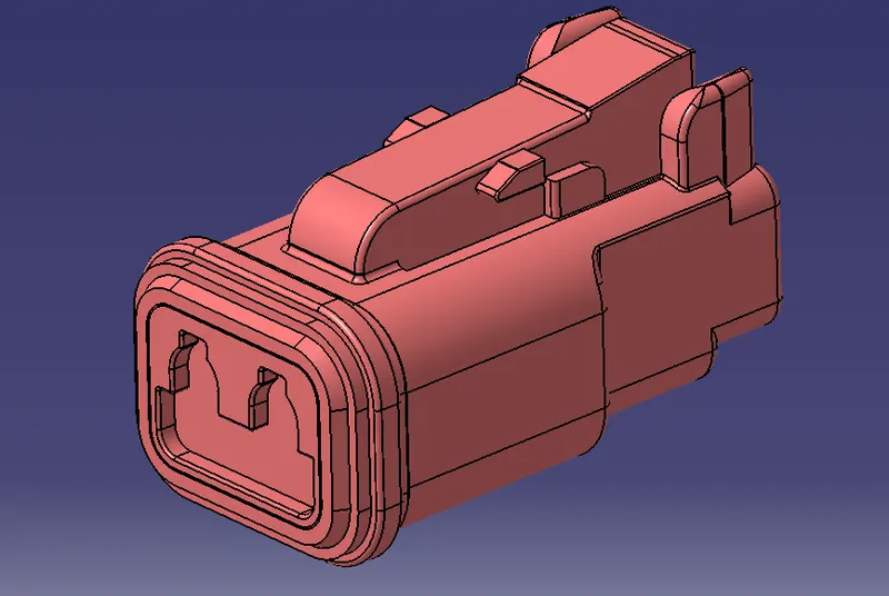
DEfine the part as the electrical connector by providing the number of terminations
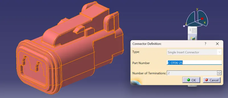
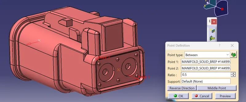
The connector connection point:
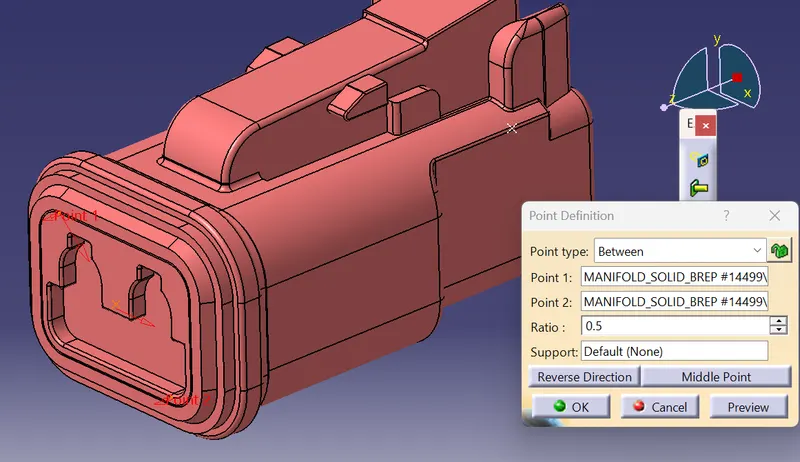
The bundle / wire connection point:
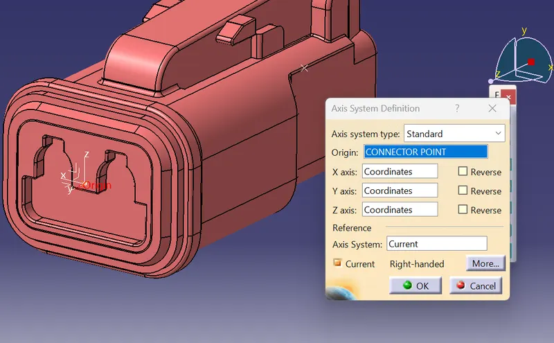
The mating axis system:
save the component
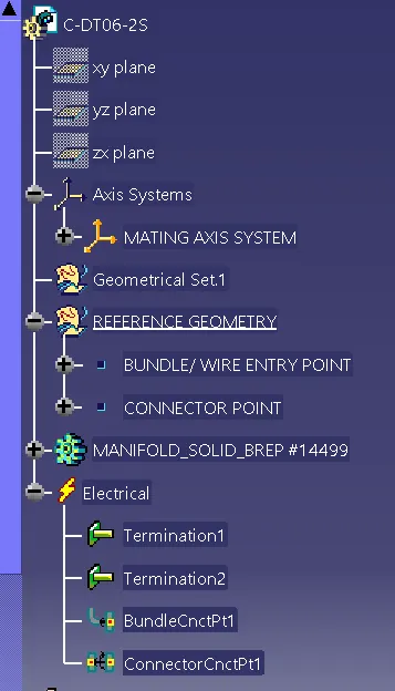
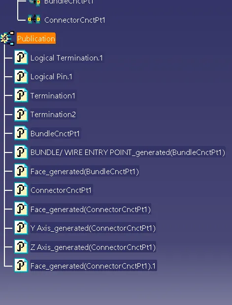
The tree structue is
- DT06-08SA
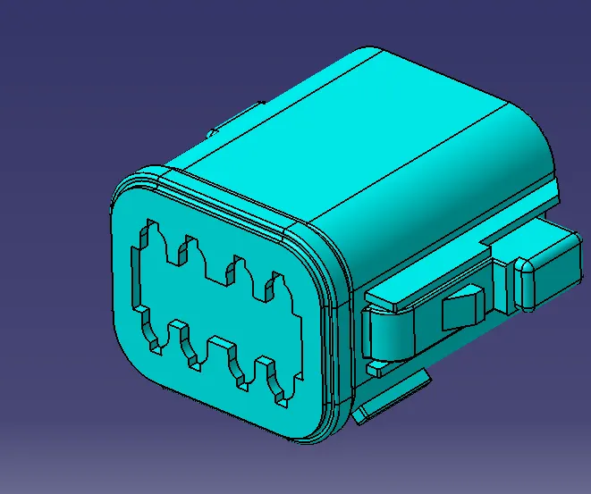
DEfine the part as the electrical connector by providing the number of terminations
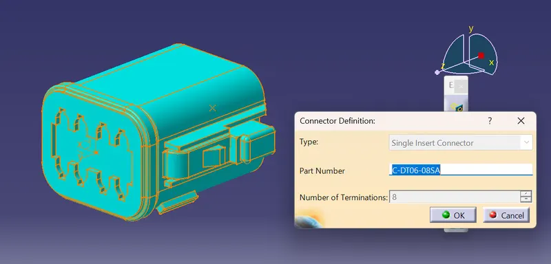
The connector connection point:
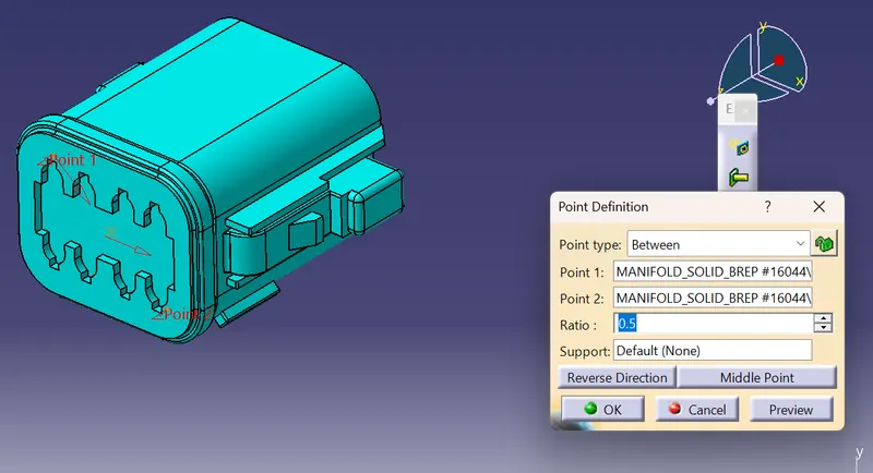
The bundle connection point is
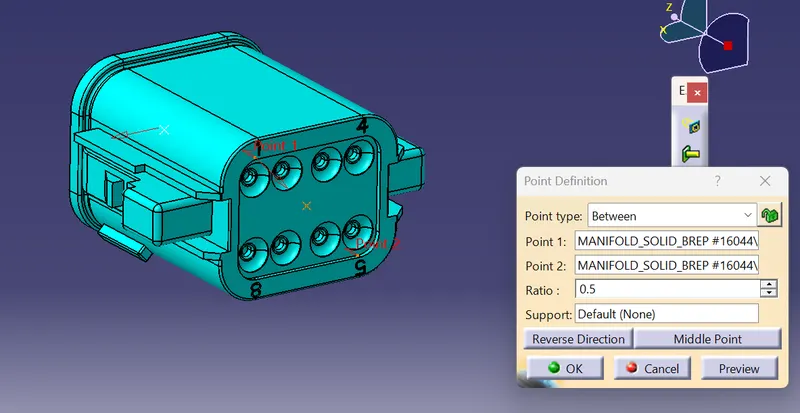
The mating axis system is
Save the component
The tree structure is
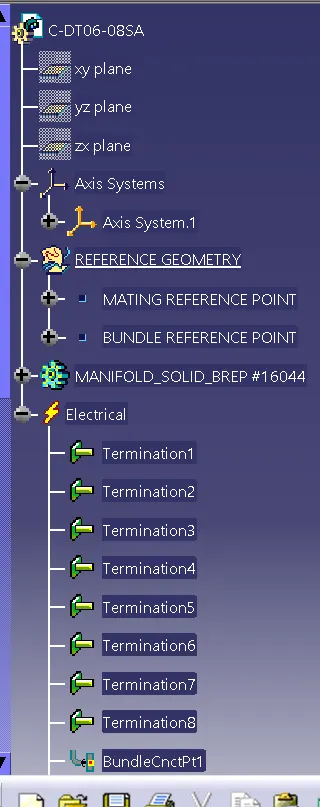
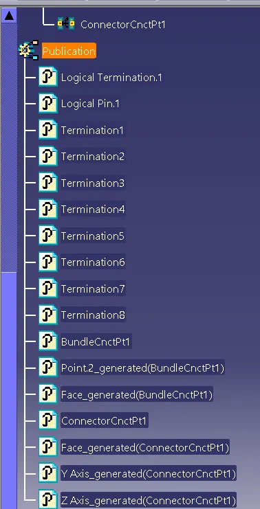
- Adding the required background data in the context assy:
Now add the base metal platre for the propper assembly routing of the wiring harness
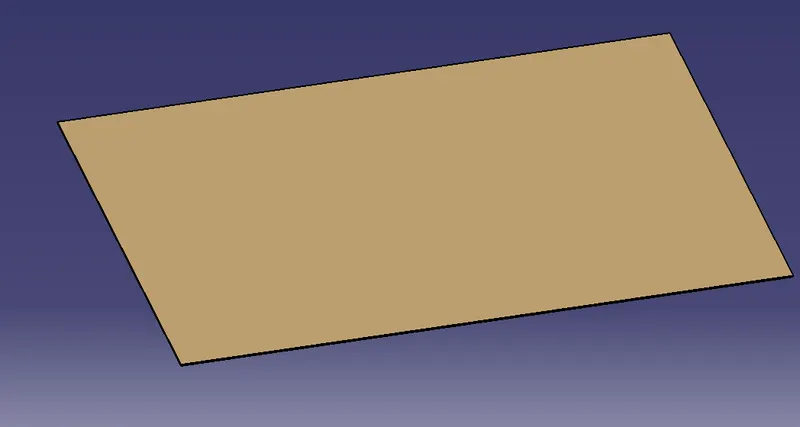
Now place the elecrical connector components as mentioned in the question
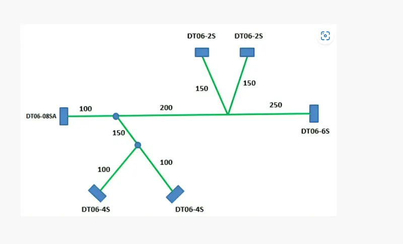
For this use the manipilation , snap, compass features
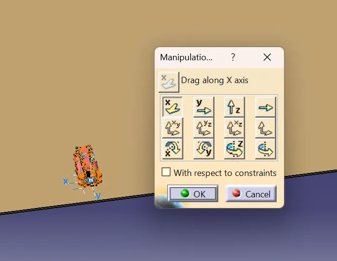
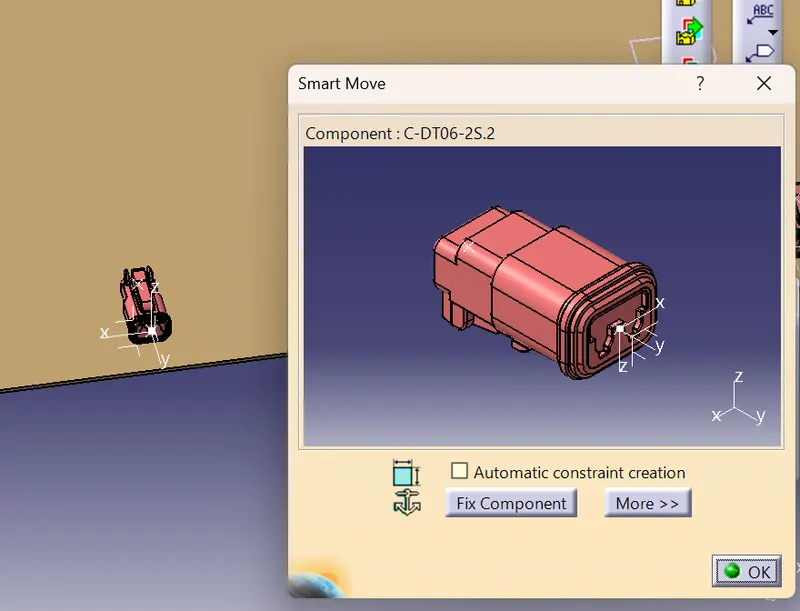
After placing the assembly will be like
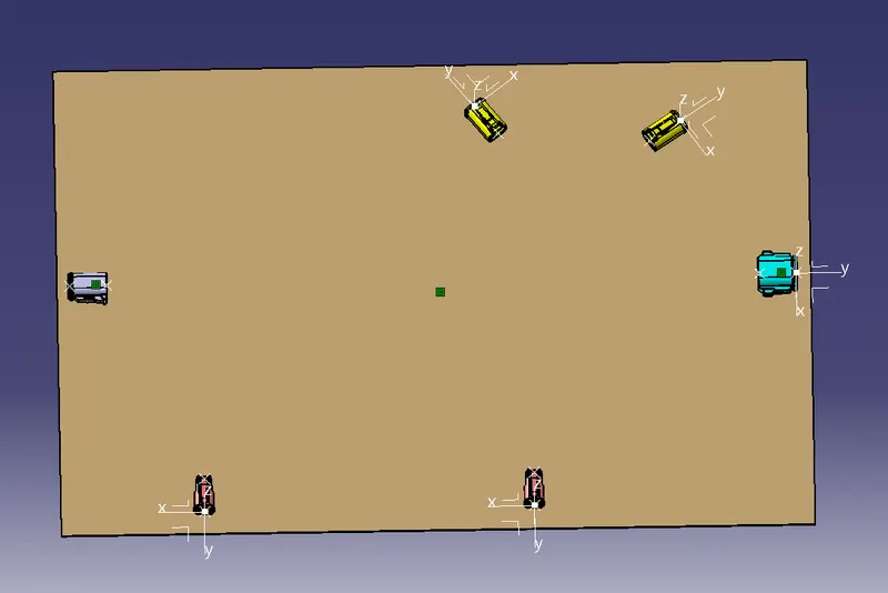
Now go to the wiring harness assembly workbench and define the geometical bundle as the geometic bundle electric

Now the symbol changes then go to the multi branchable command
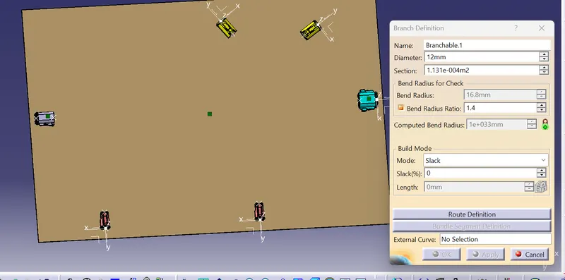
Provide the diameter of the routing bundle as the 10MM and the bent radius as the 1.4
Then define the route defnition and the select the two bundle that we want to route the bundle
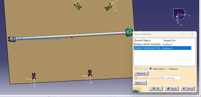
Now define the branch point by providing the necessary length on the bundle
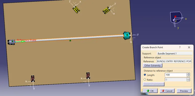
Now go to the branch defnition feature to connect the other related connectors as shown in the challenge
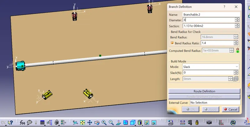
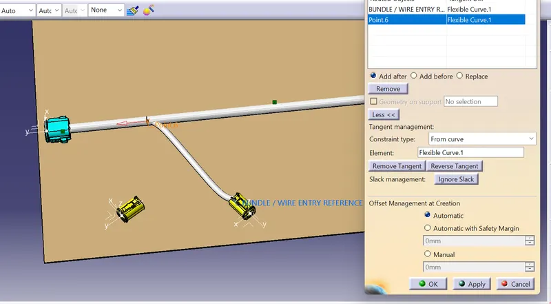
Now continue for the other components and the final bundle routing assembly is
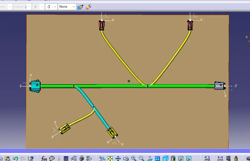
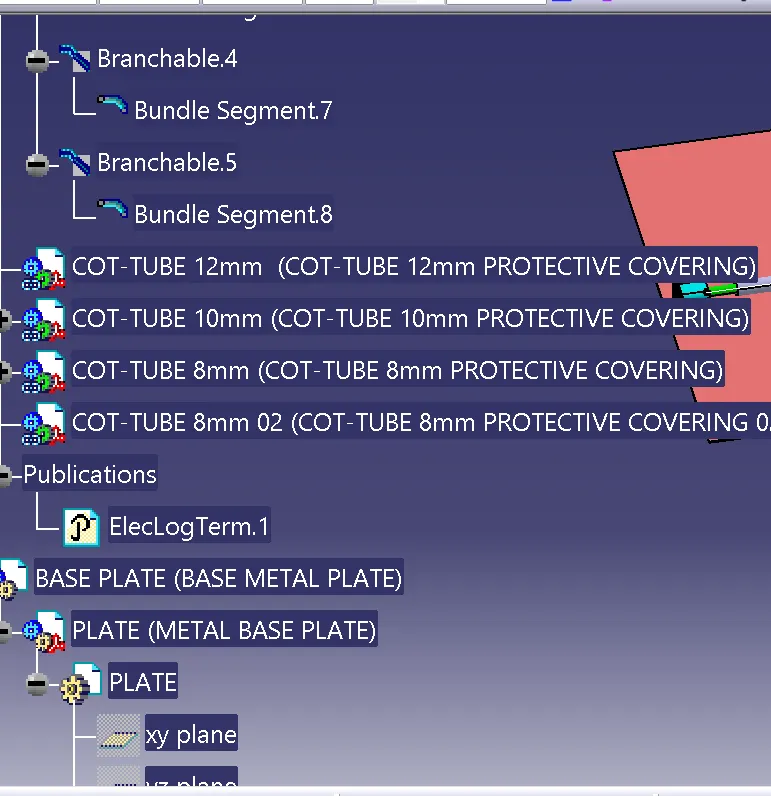
Now add the protective covering with the cot tubes of 12mm, 10mm, 8 mm
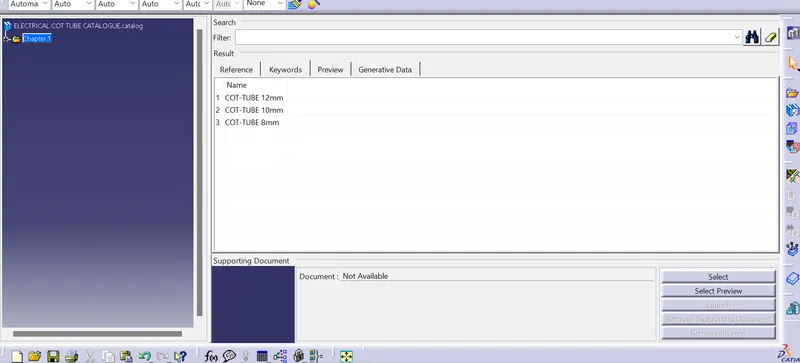
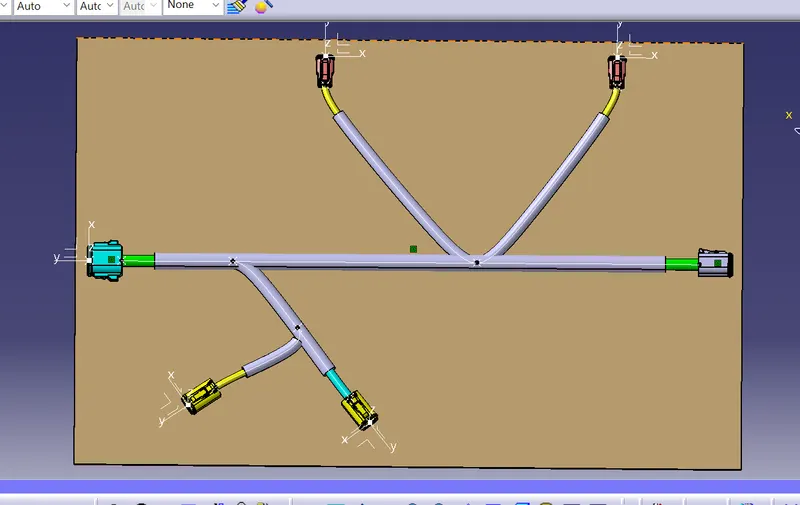
Now add the protective covering with 30mm gap from the connector
so the final object is
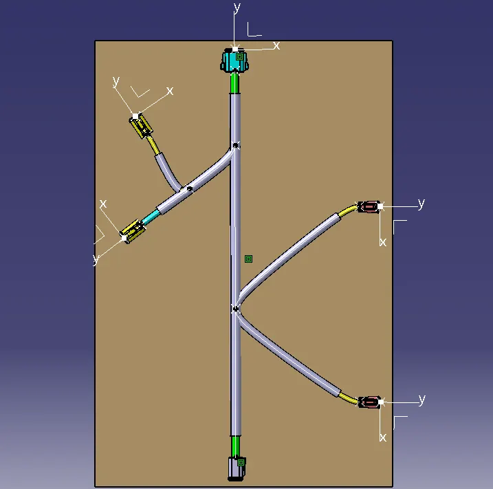
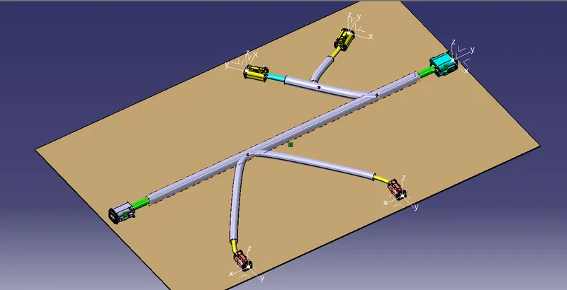
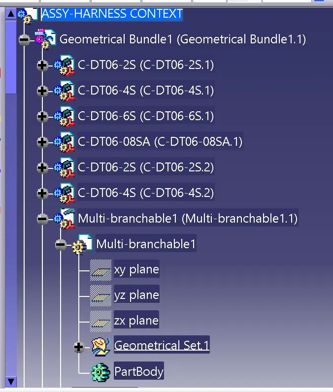
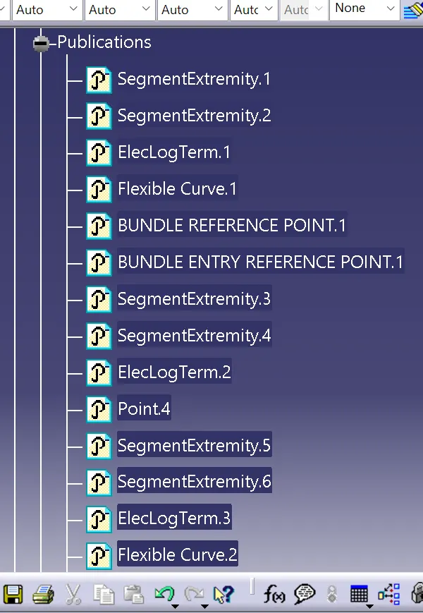
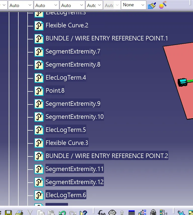
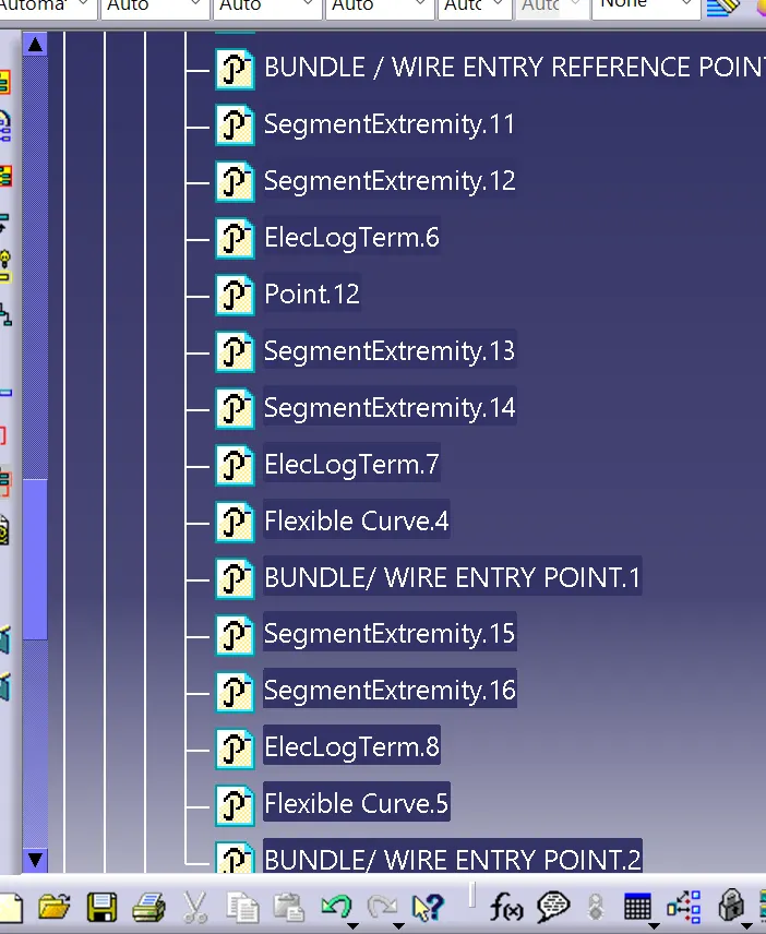
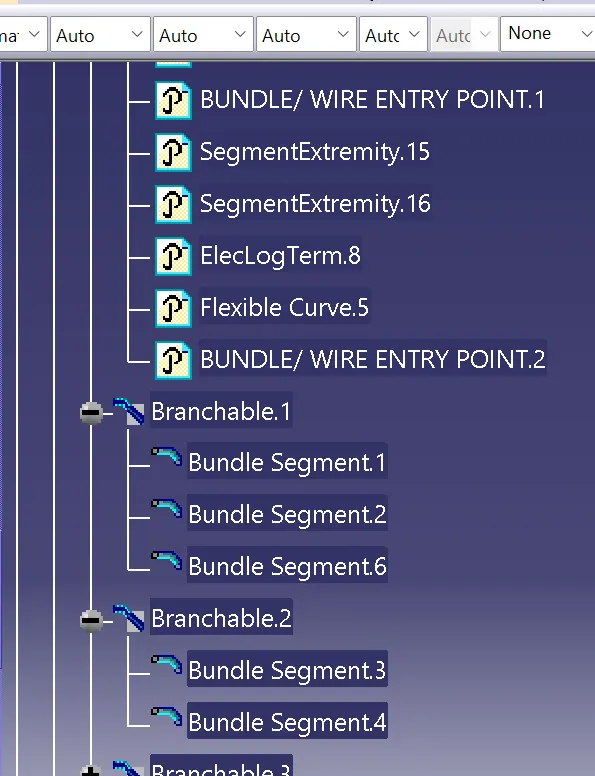
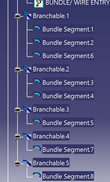
The tree structure: