Wiring harness design in CATIA V5 - 3D modeling Week 4 Challenge
'Wiring harness design'
Wire harness design is the process by which an engineer evaluates the requirements of an electrical part of system, given available physical space to create an assembly of wires to deliver power and information as needed. The design must connect all necessary components and not interfere with other systems critical to the operation and purpose of the product.
Wiring harness routing: It provides the desired path of wiring harness into given vehicle environment by applying set of design rules and industrial standards.It also have a protective covering wrapped around it.
Input:
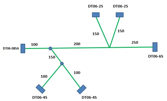
Master Section for the routing
Deutsch connectors used in this harness are as follows:
- DT06-2S (QTY-2)
- DT06-4S (QTY-2)
- DT06-6S (QTY-1)
- DT06-8S (QTY-1)
STEPS:
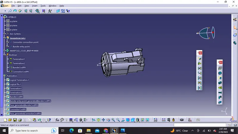
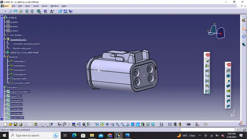
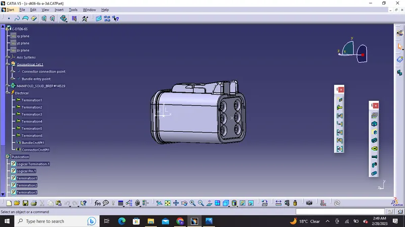
1) Let us define all the the geometrical and electrical parameters of all connectors in the electrical part design workbench in CATIA V5.
1) DT06-2S
2) DT06-4S
3) DT06-6S
4) DT06-08SA
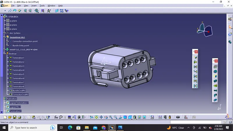
Tree Structure:
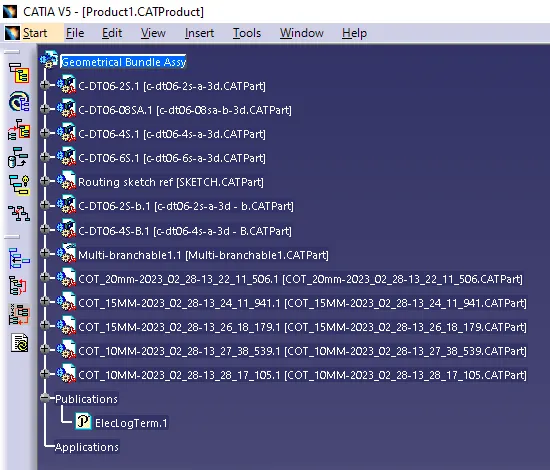
2)Then we will create al a product file in assembly design and name it as "geomrtrical bundle assembly" in which we will add all the connectors which are electrically defined
Then we will convert mechanical assembly design into electrical assembly by using "Geometrical Bundle" command.
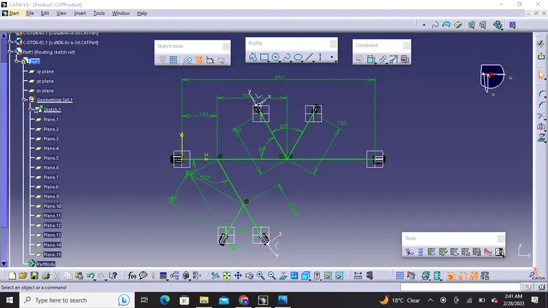
3) We will add a part to product and then draw a fully constraint sketch as per master section
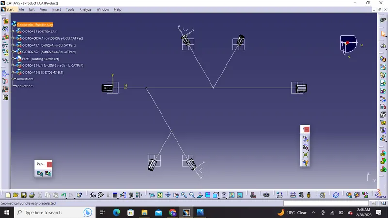
4) we will place all connectors on the points with the help of tools like smart move, snap etc
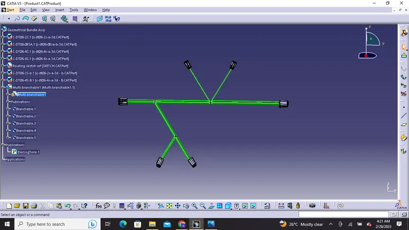
5) Furthermore we will Create Bundle segments and branching points between the connectors.
Note :Connectors DT06-8S and DT06-6S will have a harness bundle diameter of 15mm ( As per the requirement) rest we can have of 10mm and 5mm.
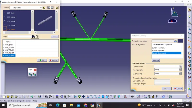
6) we will add protective coverings from the previously build catalogue for cot tubes
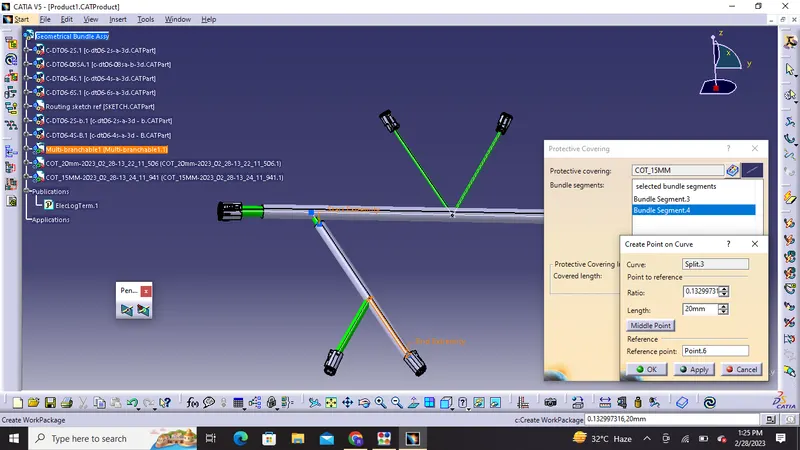
7) We can adjust the distance of cot tubes from end extremity or start points.
Output:
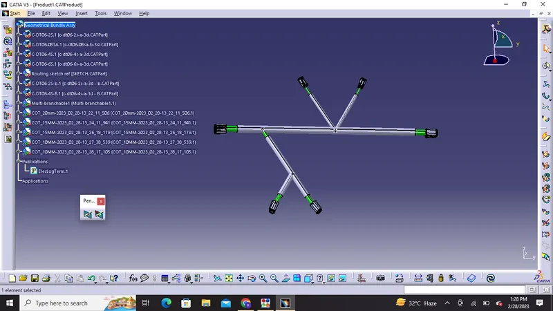
This is the final harness bundle assembly design
Thank You!