Wiring harness design in CATIA V5 - 3D modeling Week 4 Challenge
Wiring Harness Assembly- Routing procedure
Aim:- To define the connectors and catalogues electrically and route the mutibranchable bundle segments according to the given schematic diagram.
Workbenches used:
Mechanical part design
mechanical Assembly design
Electrical part design
Electrical assembly design
Electrical harness assembly
Electrical harness installation
Schematic wiring Diagram:
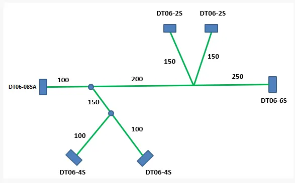
Connectors used:
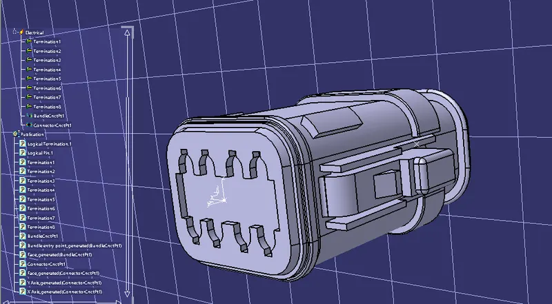
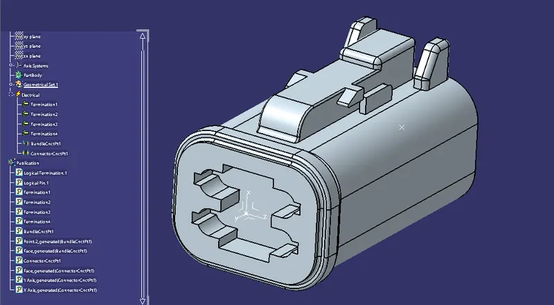
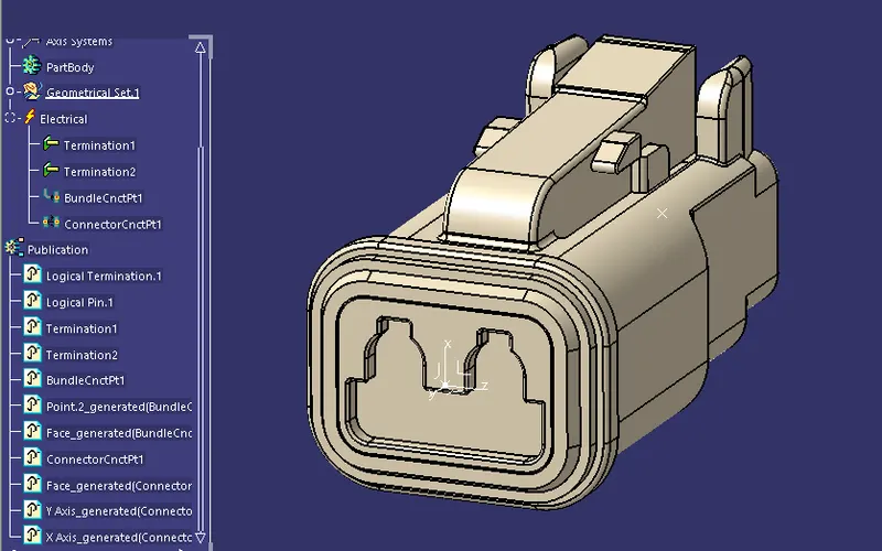
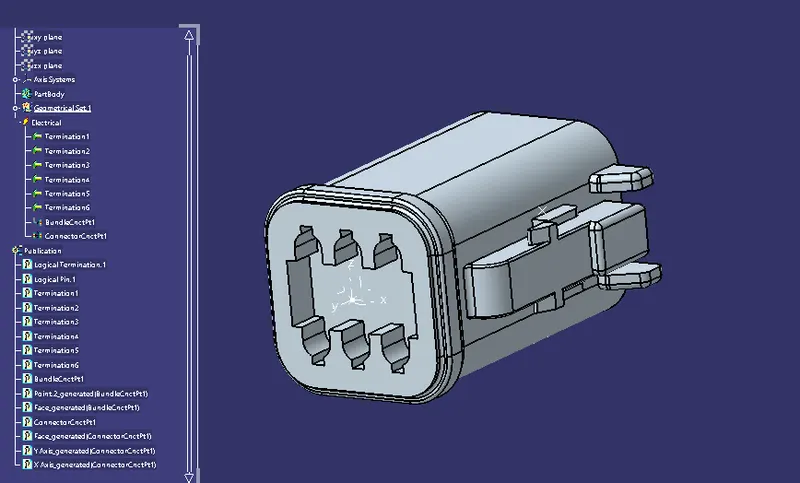
- All connectors are electrically defined using electrical part design, including bundle connection point and connector connection point.
- Axis systems are provided in the proper way, that the y axis facing to the bundle connection point.
- After definition, all are added to a single catalogue.
- DT06-08SA
- DT06-4S
- DT06-2S
- DT06-6S
Electrical harness design:
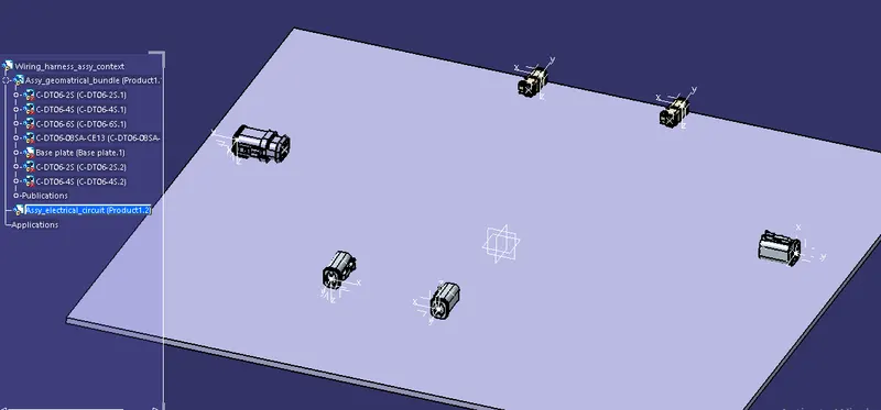
- Placing the connectors imported from catalogues.
-Arranging the connectors as per the given schematic in the assembly design workbench. Moving and rotating using manipulation commands at the distance mentioned in the diagram.
-Then switch to electrical harness assembly. The product file needs to assigned as a gemetrical bundle using the geometrical bundle tool. It will add the electrical definition into the publications.
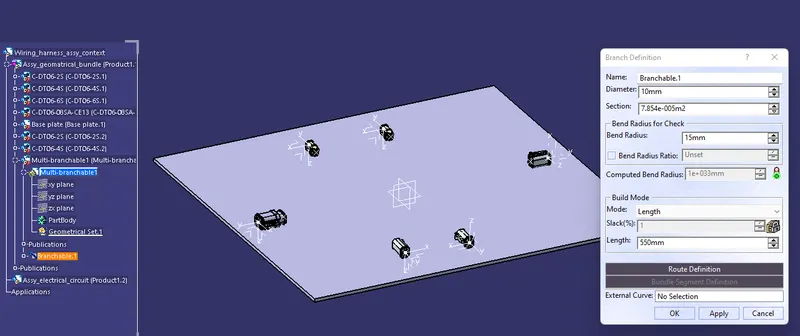
- Using the Multi branchable document tool, add braches by connecting the main connectors.
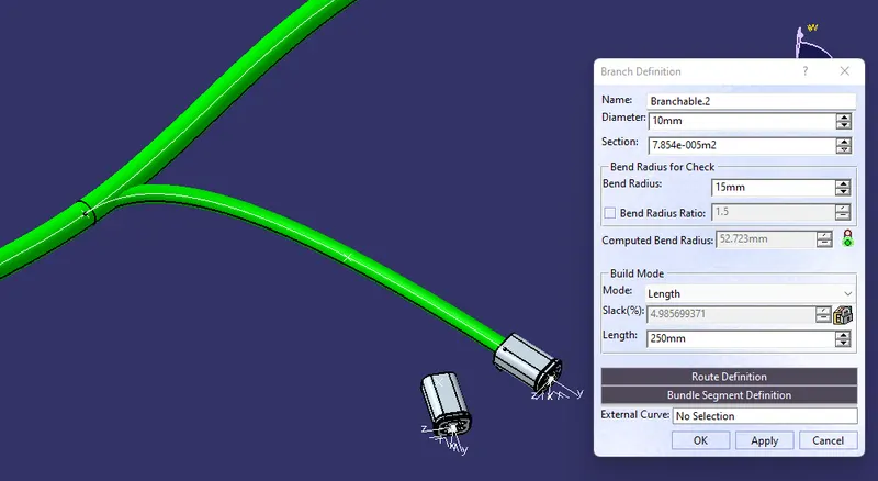
- In the branch definition, we can define diameter and length of the bundle. Diameter of the main branch segment is taken as 15 mm.
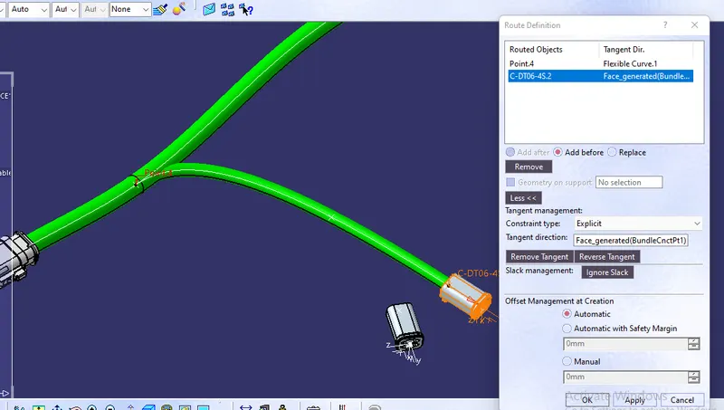
- Use the route definition dialogue box to pick the main connectors and thier connection points as shown.
- This will change the workbench to Electrical harness installation, where, we can define budle segments and their branches.
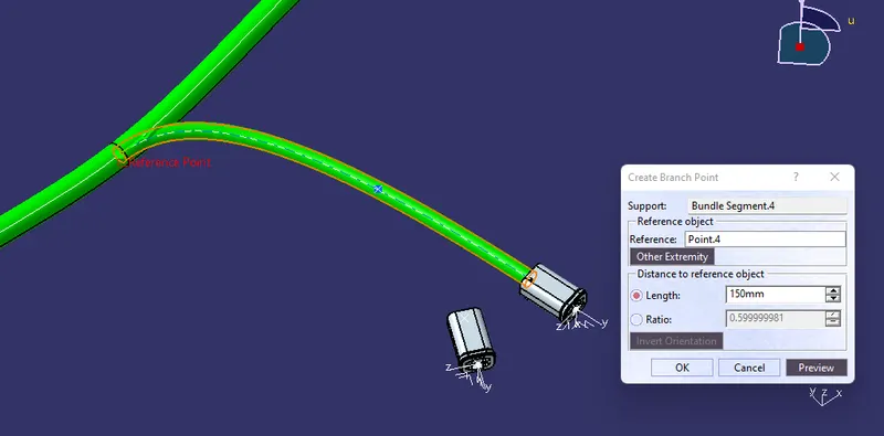
- Using the 'add branch points' tool, make branch segments at desired lengths.
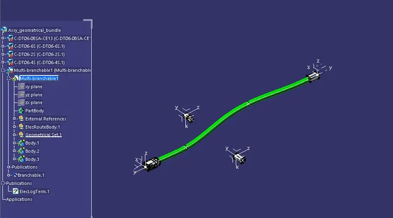
- These segments are utilised for creating sub branches to the remaining connectors.
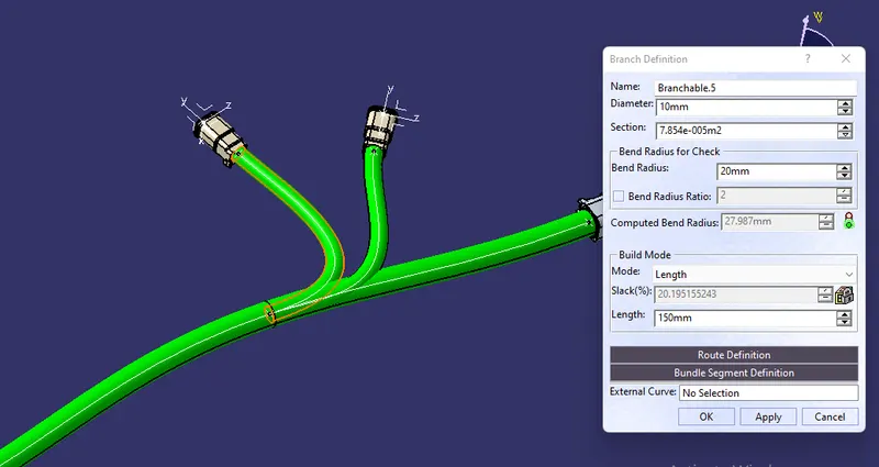
- Branches are made using the 'branch definition' tool in the same workbench.
- Sub branches are in 10mm dia and length as per the diagram.
- Route the wires as shown by assigning proper tangent direction from the branch points.
- Sub branches can be again splitted to provide more branches using the same method.
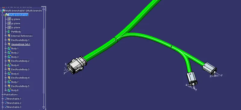
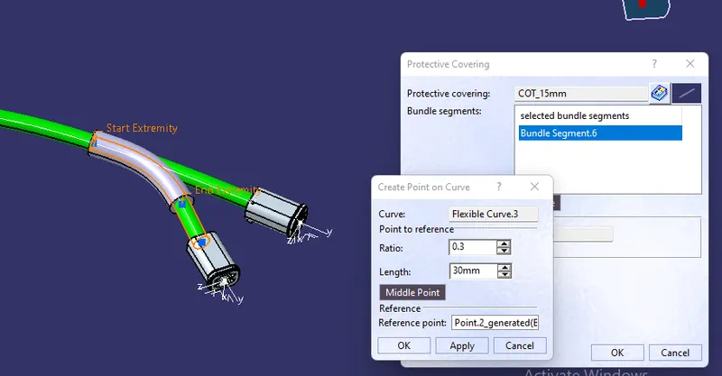
- Using the 'protective covering' tool, add protective coverings to the segments.
- Protective coverings are previously defined in a catalogue.
- End extremity is given as 30mm.
Finalization:-
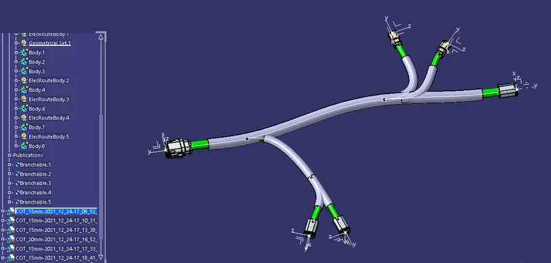
Conclusion:- Using this method, we will be able to define connection definitions in a 3d environment of an automotive for different applications.