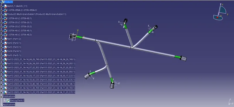
Wiring harness design in CATIA V5 - 3D modeling Week 4 Challenge
1. Defining Deutsch DT06 – 08SA:
- The connector is downloaded from the given link
In Part Design Work Bench:
- The Connector Connection Point and the Bundle Entry Point are defined on their respective mating faces
- The required axis system is defined for the connector connection point
- Then the Work Bench is changed to 'Electrical Part Design'
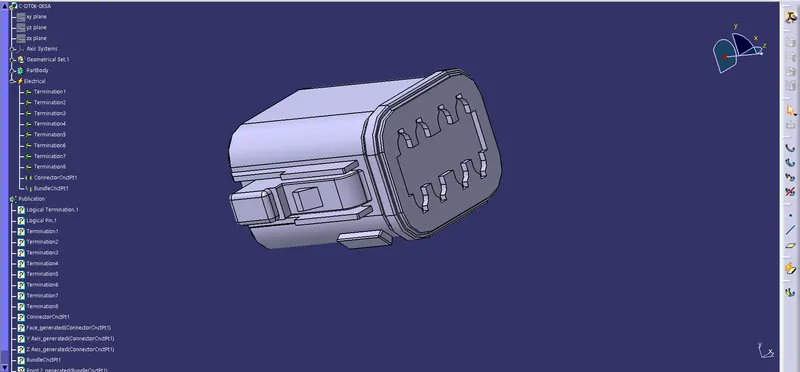
In Electrical Part Design Work Bench:
- The connector is defined as a connector with
- Type: Single Insert Connector
- Part Number: C-DT06-08SA
- Number of Terminations: 8
- Then the connector connection point is defined with
- Representation: Connector_Connection_Point
- Contact: Mating Face
- Coincidence: Y-Axis
- Orientation: X-Axis
- Then the Bundle Entry Point is defined with
- Representation: Mating Face
- Point: Bundle_Entry_Point
- Initial Condition: Mating Face
2. Defining Deutsch DT06 – 6S:
- The connector is downloaded from the given link
In Part Design Work Bench:
- The Connector Connection Point and the Bundle Entry Point are defined on their respective mating faces
- The required axis system is defined for the connector connection point
- Then the Work Bench is changed to 'Electrical Part Design'
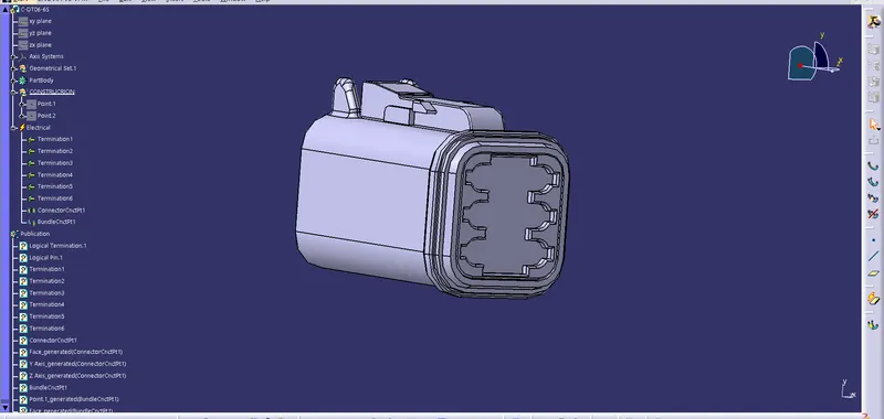
In Electrical Part Design Work Bench:
- The connector is defined as a connector with
- Type: Single Insert Connector
- Part Number: C-DT06-6S
- Number of Terminations: 6
- Then the connector connection point is defined with
- Representation: Connector_Connection_Point
- Contact: Mating Face
- Coincidence: Y-Axis
- Orientation: X-Axis
- Then the Bundle Entry Point is defined with
- Representation: Mating Face
- Point: Bundle_Entry_Point
- Initial Condition: Mating Face
3. Defining Deutsch DT06 – 4S:
- The connector is downloaded from the given link
In Part Design Work Bench:
- The Connector Connection Point and the Bundle Entry Point are defined on their respective mating faces
- The required axis system is defined for the connector connection point
- Then the Work Bench is changed to 'Electrical Part Design'
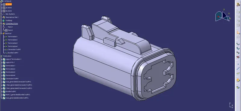
In Electrical Part Design Work Bench:
- The connector is defined as a connector with
- Type: Single Insert Connector
- Part Number: C-DT06-4S
- Number of Terminations: 4
- Then the connector connection point is defined with
- Representation: Connector_Connection_Point
- Contact: Mating Face
- Coincidence: Y-Axis
- Orientation: X-Axis
- Then the Bundle Entry Point is defined with
- Representation: Mating Face
- Point: Bundle_Entry_Point
- Initial Condition: Mating Face
4. Defining Deutsch DT06 – 2S:
- The connector is downloaded from the given link
In Part Design Work Bench:
- The Connector Connection Point and the Bundle Entry Point are defined on their respective mating faces
- The required axis system is defined for the connector connection point
- Then the Work Bench is changed to 'Electrical Part Design'
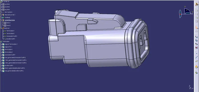
In Electrical Part Design Work Bench:
- The connector is defined as a connector with
- Type: Single Insert Connector
- Part Number: C-DT06-2S
- Number of Terminations: 2
- Then the connector connection point is defined with
- Representation: Connector_Connection_Point
- Contact: Mating Face
- Coincidence: Y-Axis
- Orientation: X-Axis
- Then the Bundle Entry Point is defined with
- Representation: Mating Face
- Point: Bundle_Entry_Point
- Initial Condition: Mating Face
Creating the required harness routing:
- A sketch create on a plane with dimensions appropriate for the dimensions of the entire harness assembly
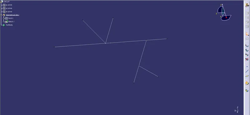
- A new product is created and named Assy_Wiring_Harness_Context
- Another new product under the Assy_Wiring_Harness_Context is created and named Assy_Geometric_Bundle
- All the connectors are imported into the Assy_Geometric_Bundle
- The positioning sketch is imported into Assy_Wiring_Harness_Bundle
- The connectors are moved and oriented on the sketch according to the requirements
- The Workbench is switched to 'Electric Harness Assembly
- A 10mm branch with a 1.4 bend radius ratio and 0% slack between connectors DT06-08SA and DT06-6S is created
- A branch point is created at a distance of 100mm from DT06-08SA
- A 2nd branch point is created at a distance of 200mm from the 1st branch point
- A 5mm branch with a 1.4 bend radius ratio and 0% slack from the 1st branch point on the main branch and DT06-4S connector is created
- A 3rd branch point is created at a distance of 150mm from the 1st branch point on the 5mm branch
- A 5mm branch with a 1.4 bend radius ratio and 0% slack between the 3rd branch point and another DT06-4S connector is created
- A 5mm branch with a 1.4 bend radius ratio and 0% slack from the 2nd branch point on the main branch and the DT06-2S connector is created
- A 5mm branch with a 1.4 bend radius ratio and 0% slack between the 2nd branch point on the main branch and another DT06-2S connector is created
- A 10mm corrugated tube protective covering is applied on the main branch with a 30mm end extremity from the connectors and a 5mm corrugated tube protective covering is applied on the sub-branches with a 30mm end extremity from the connectors by clicking on the 'Protective Covering' icon from the 'Electric Harness Assembly' workbench.
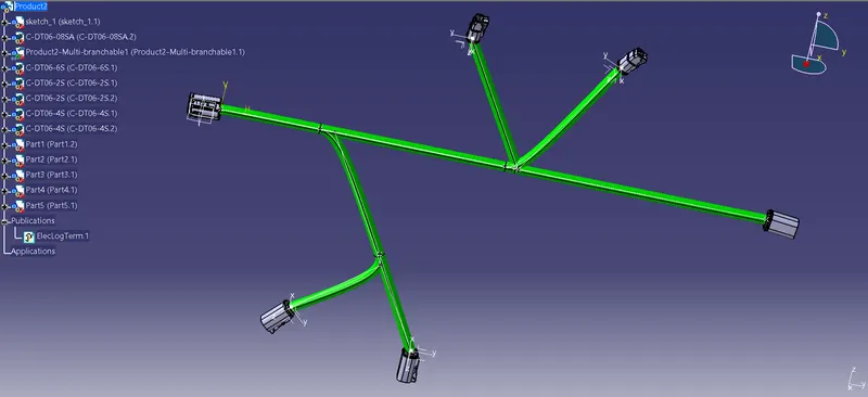
Adding the Corrugated:
Firstly create the desired corrugated tube from the Electrical part design work bench by selecting the defien protect part command and also select the desired diameter where i have selected 10 mm.