Wiring harness design in CATIA V5 - 3D modeling Week 4 Challenge
ANSWER:
Preparation Of Harness Assembly
As we are done with the wiring harness component design, it is time to prepare the product assembly for the given harness.
Wiring Harness Product Assembly Contains:-
- The Harness Context Assembly:- This is the top-level product file that contains the harness geometrical bundle/assembly and the wire harness electrical bundle.
- Geometrical Bundle:- This sub-level product file is the wire harness product that contains all of the harness components clips, connectors, clamps, actual physical bundle segments, and branches.
- Electrical Bundle:- This sub-level product file contains all of the electrical circuit information.
First, we can download the given connectors from te.com
- DT06-4S
- DT06-6S
- DT06-2S
- DT06-08SA
Before you can route the wiring harness you will need an electrically defined one. Components to route the harness from, electrical harness connectors to route the harness to, and also some electrical defined harness connectors between to fix your harness route. Then we can create the electrical properties for the given connectors.
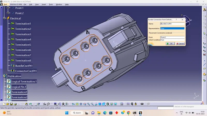
AS PER THE BELOW SHOWN FIGURES, WE HAVE TO PREPARE THE CONNECTORS:
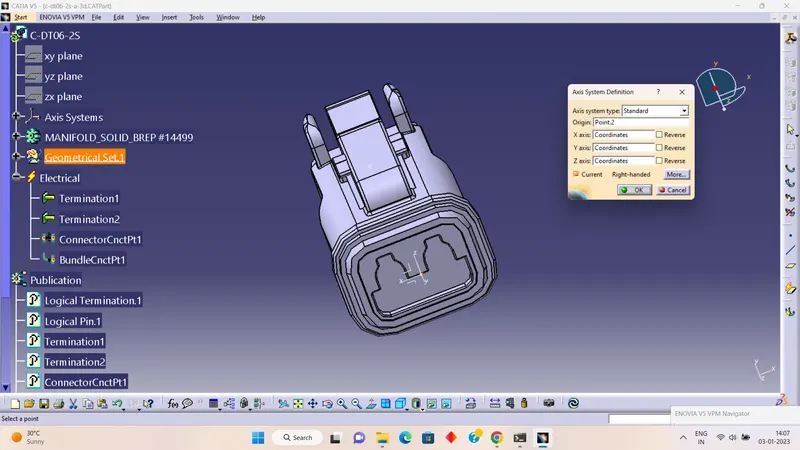
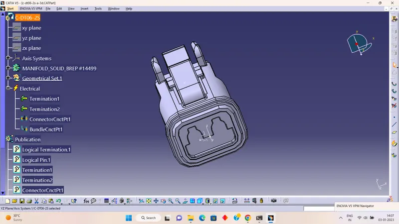
- DT06-2S
- Firstly we have created the required geometrical parameters
- defined part as a connector
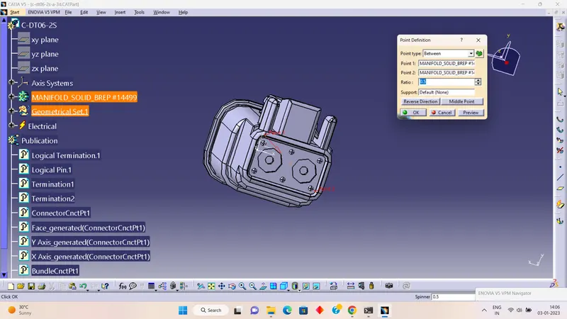
- defined bundle connection point
- defined connector connection point.
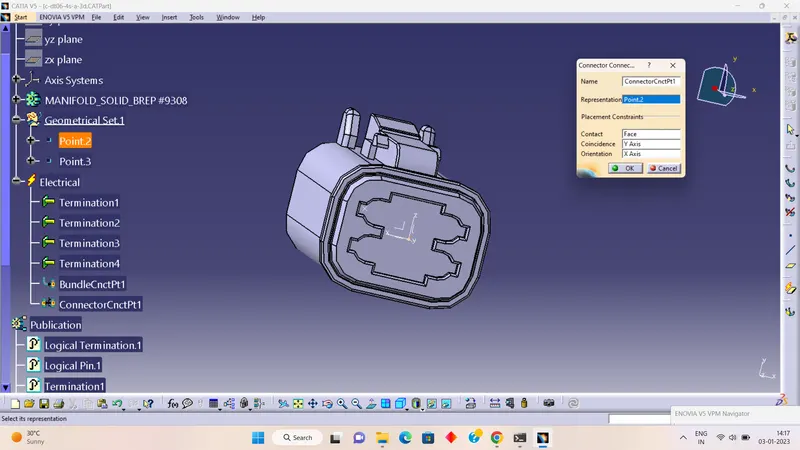
- DT06-4S
- Firstly we have created the required geometrical parameters
- defined part as a connector
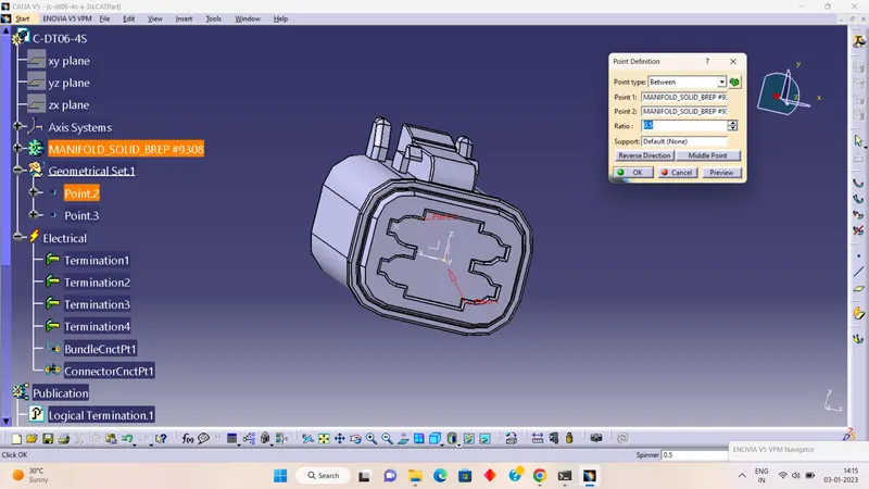
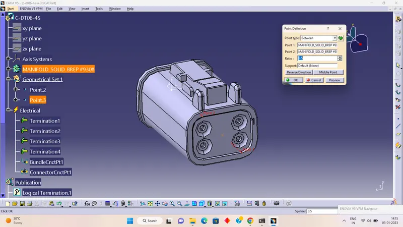
- defined bundle connection point
- defined connector connection point.
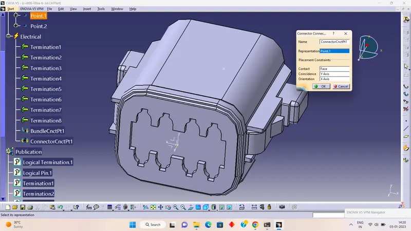
- DT06-8S
- Firstly we have created the required geometrical parameters
- defined part as a connector
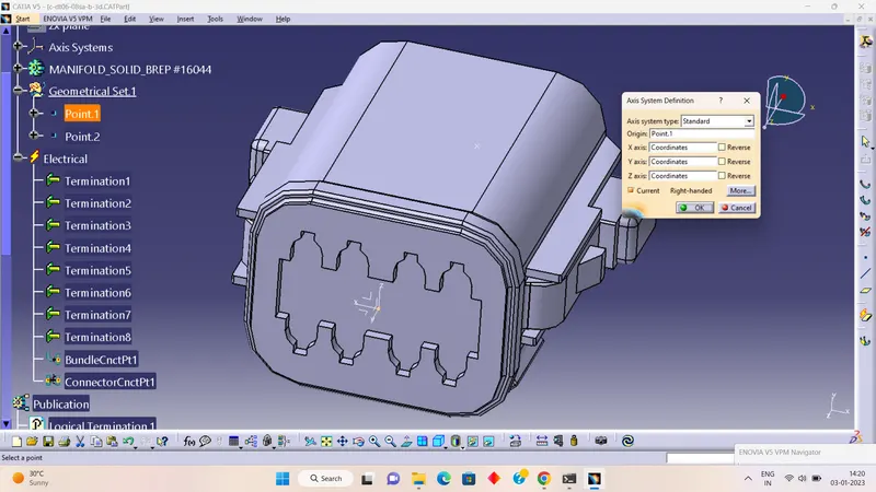
- defined bundle connection point
- defined connector connection point.
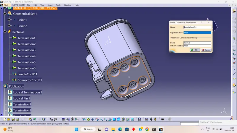
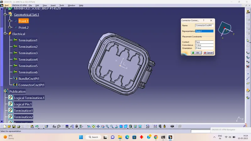
- DT06-6S
- Firstly we have created the required geometrical parameters
- defined part as a connector
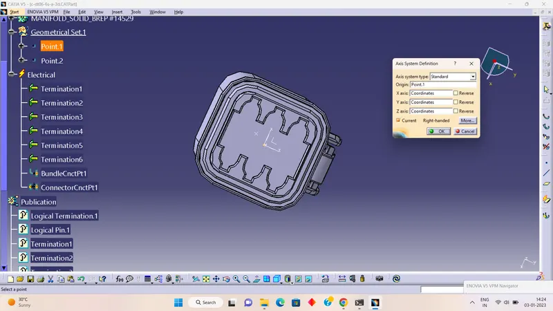
- defined bundle connection point
- defined connector connection point.
Creating the Wire Harness Geometrical Bunde
Follow the below steps to create a geometrical bundle /harness assembly
- Create a New Product File. First, we can click on file next select the New and lastly select product
- Again change the product part number to" Assy_Geometrical_bundel".
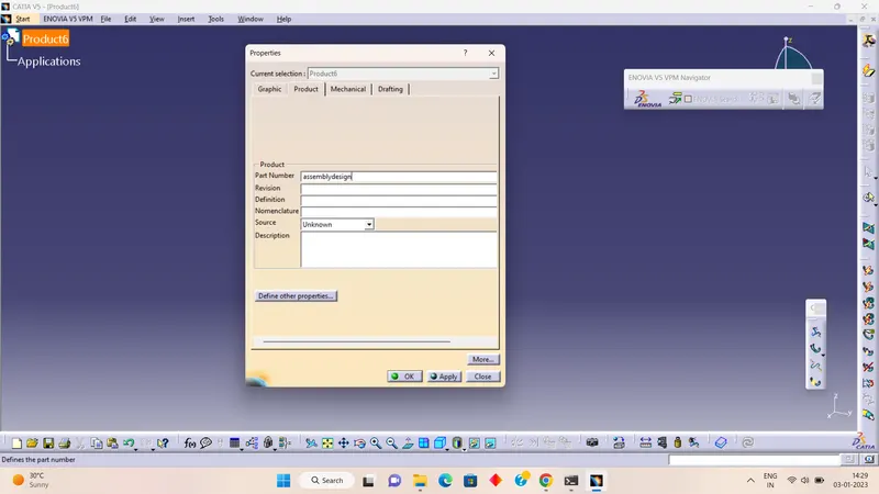
- When creating the wire harness bundle segment you are first required to insert the electrical components that you need to route the wire harness from and to.
- Before you can route the wire harness you will need an electrical definition.
- This data should also be removed from your context assembly before saving.
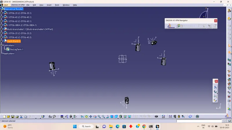
- Switch to the Electrical Harness Assembly Workbench icon.
- Then select the Geometrical Bundle icon. Then select the product from the model tree(what we created) product icon in the model tree is changed now and the name changed to "Geometrical Bundle"
- Our assembly is changed from mechanical assembly to electrical assembly.
- Next we click on bundle definition the multi-branch able and publications are added to our assembly.
- You must now place each electrical part into its correct positioning in your geometrical bundle production file.
- There are five main functions for moving and positioning the electrical wire harness components. Those are in the assembly design workbench.
ALSO, WE CAN USE SKETCHING IN MECHANICAL ASSEMBLE DESIGN:
1) Manipulation.
2) Translation & Rotation
3) Snap
4) Smart Move
5) Compass
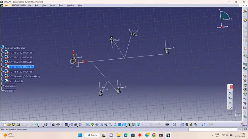
In our bundle harness assembly, the diameter of the bundle is 15mm. Then we click one bundle definition here we enter the diameter as 15mm and the bend ratio as 1.4 next click on slack percentage is 0. Then click route definition here we can select the first connector and click add after then select another connector then click on a reverse tangent and click ok.
WE HAVE GONE FOR THE BUNDLE HARNESS ASSEMBLY:
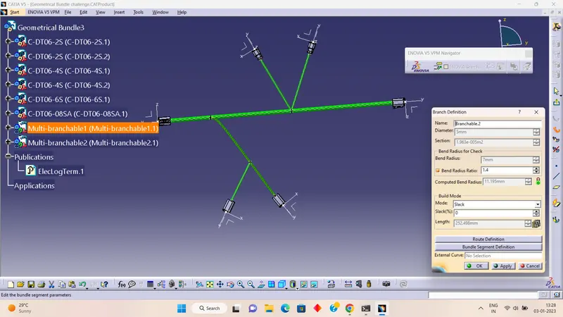
- After placing the connectors we started the harness
- by selecting the branch definition we have selected respected length
- then we selected the connector for the routed definition to connect the connectors with the bundle wire harness
- added branch point by selecting the add branch point at a respected distance and created branch point
- by selecting the respective point and connectors completed all the bundle harnesses as per model requirements
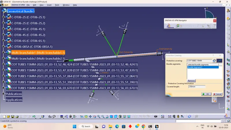
- WE HAVE GONE FOR PROTECTION COVERING;
- We prepared the required cot tubes and stored them in a catalog document
- add the family option used to create the document
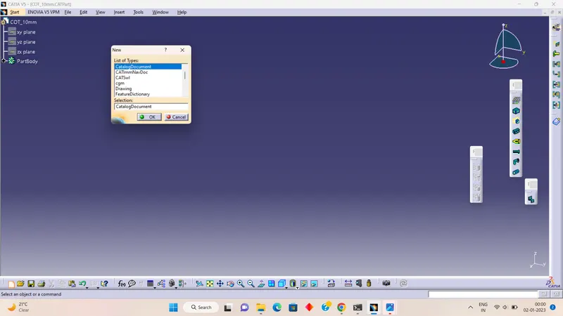
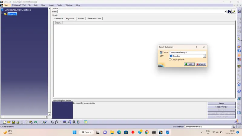
- we have added the respected length of cot tubes and prepared the covering for the entire harness
- we have kept a minimum 30mm end extreme from the connectors.
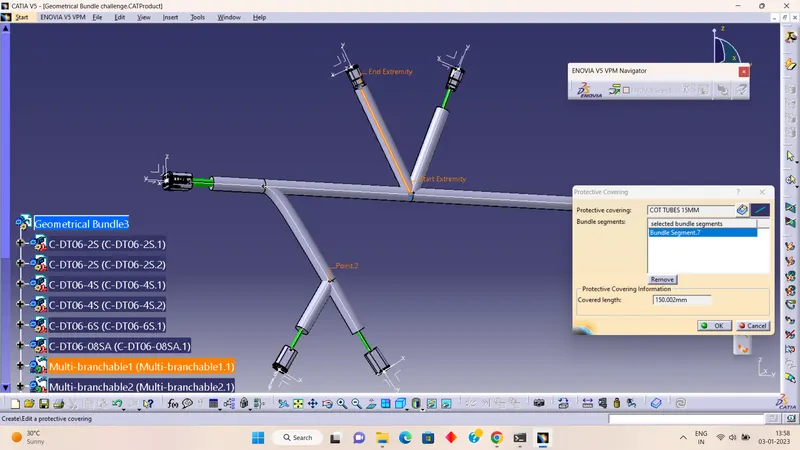
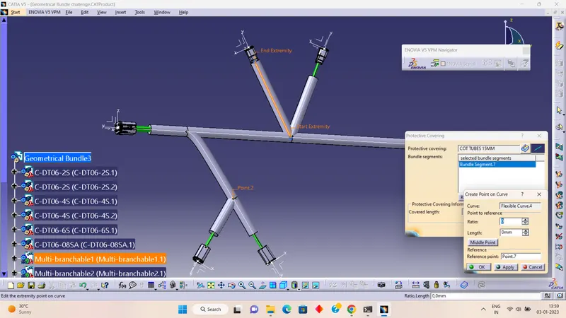
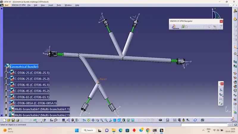
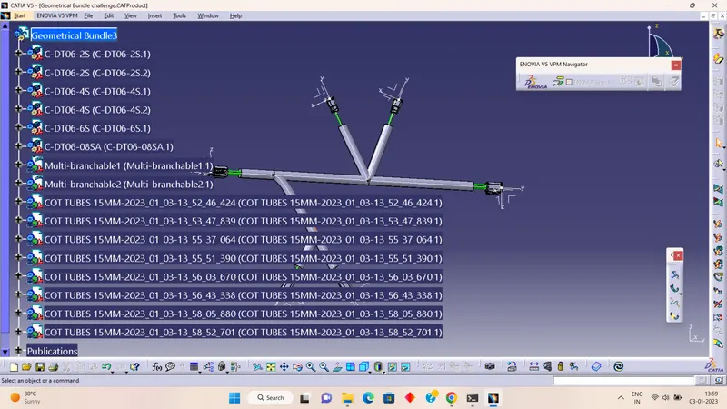
We prepared our assembly as per our requirements.