Wiring harness design in CATIA V5 - 3D modeling Week 4 Challenge
In this challenge a wiring harness bundle assembly is created.
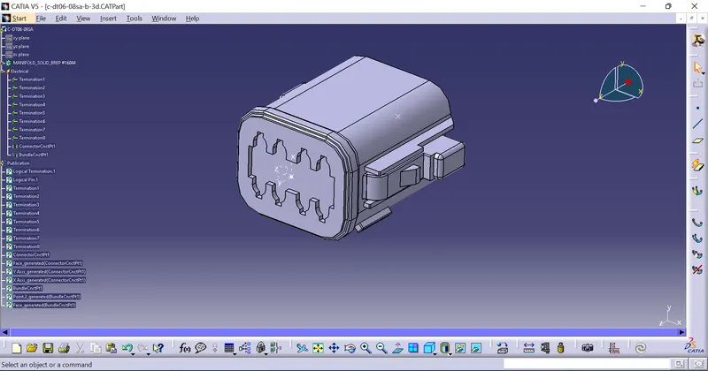
The connectors downloaded and are defined electrically as shown below.
- the connector 3D model is download as .stp from the website.
- This is stp file is opened in catia and saved as CATpart file.
- Two points are defined one at the front of the connector and one at the rear of the connector at the center of the faces.
- An axis system is defined at the front of the connector where it should be connected with the counterpart.
- Now we have to switch to electrical part design.
- Define the part as a connector.
- Define the connector connection point and the bundle entry point.
- Add the connector into the connector catalog.
- In a similar way all other three connectors are defined.
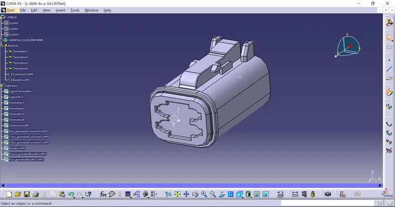
DT06-4S
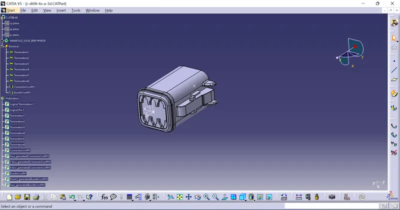
DT06-6S
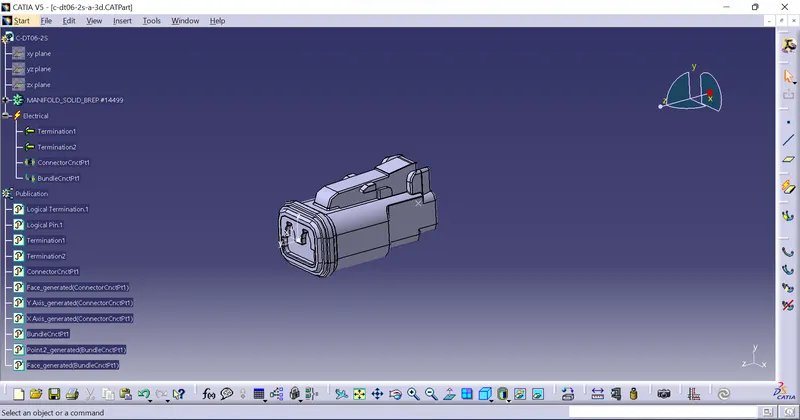
DT06-2S
DT06-08SA
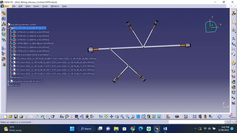
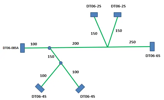
now we have to create a new harness with the layout shown below.
So first you start a new product file.
Then in that product file start a new product file as a sub level as shown in image below.
The top level product file his name task wiring harness context assembly.
The sub level file is named as geometrical bundle assembly.
The locations of the parts or connectors can be referenced to another part file and the locations can be given a sketch.
This locations sketch file is a .CATpart file which is added into the Context assembly and can be later removed once all the connectors are placed.
Now open the geometrical bundle file in a new window.
Add all the electrically defined connectors into the geometrical bundle product file.
Now switch to mechanical assembly design and using the move toolbar tools move the parts to the appropriate position.
Now again switch back to electrical harness assembly.
The assembly is still a mechanical assembly.
We have to convert it into an electrical assembly using the "geometrical bundle" tool
After clicking on the "geometrical bundle" tool select the "geometrical bundle assembly" file name in the tree.
Now the assembly file is defined as an electrical assembly.
Now we can add bundles between connectors by clicking on the "Multi branchable document" tool.
When we click on the "Multi branchable document" tool the assembly will be switched to "Electrical harness installation" mode.
This way we can add the main branch between the main connectors.
Then additional branches can be created by creating cutting points in the main branch using the "Add branch point" tools
we can add a new branch from this branch point do another connector using the "branch definition" tool.
When we are rooting the harness using the branch definition tool we can control the tangency at both ends of the harness.
Now exit from the electrical harness installation back to electrical harness assembly
After all the branches and branch points are added we again add corrugated tubes using the "protective covering" tool by selecting the protective covering catalogue and selecting the respective protective covering required.
The finished assembly is shown in the image below.