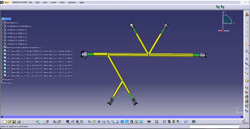
Wiring harness design in CATIA V5 - 3D modeling Week 4 Challenge
WIRING HARNESS DESIGN STEPS
1, Downloaded all the required connectors from www.te.com and defined all the connectors Ellectrically.
2, Created a layout of the given harness by using Lines with proper length as per the question.
3, Opend the Product file of the layout and ther by pasted all the required connectors also.
4, Arranged the connector by using tools like - Compass, Manipulation tool, in smart tool Smart move tool.
a, Befor using Snap tool right click on the connetor and click on Representations - and activate Design Mode
b, Befor using compass for align the connector make sure click on the connector and in active condition from the tree.
All the alligning of the connector with the reference lines are done in the Assembly Desin workbench
5, For the bundle creation between the connectors switch to Ellectric Harness Assembly work bench. Then activate the product Electrically by click on Geometrical bundle tool and click on the toop most of the produt tree,for creating wiring bundle between connectors click on Multi-Brancheble Document tool,that time CATIA automaticaly switch to Electrical Harness Instalation work bench. After click on the Multi-brancheble Document tool popup a window and give the diameter,Bendin radius as 1.4 then click on Define branch tool and select the connectrs and whataver points to be connect with the wires and click apply and click ok. Click on Protuctive covering tool for apply COT tubes on the wiring for the protuction