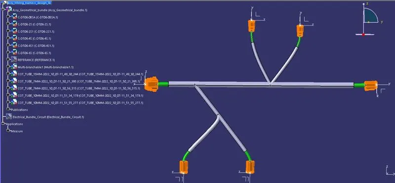
Wiring harness design in CATIA V5 - 3D modeling Week 4 Challenge
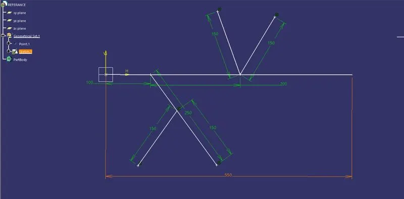
Q1. Route the following harness layout in the Electrical workbench. Make assumptions for harness bundle diameters. Use the Following connectors as shown in the layout diagram.
Add protective covering on all branches connected to DT06-2S & DT06-4S connectors. Keep end extremity at 30mm (from connectors end)
Aim:
1) To Route the following harness layout in the Electrical workbench.
2) Add protective covering on all branches connected to DT06-2S & DT06-4S connectors.
3) Keep end extremity at 30mm (from connectors end)
4)Make assumptions for harness bundle diameters
Given:
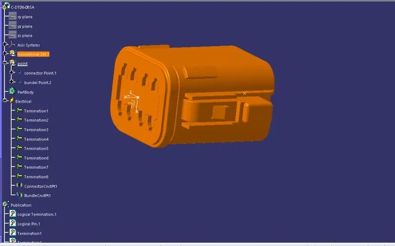
CAD data of the following Connectors:
- DT06-4S
- DT06-6S
- DT06-2S
- DT06-08SA
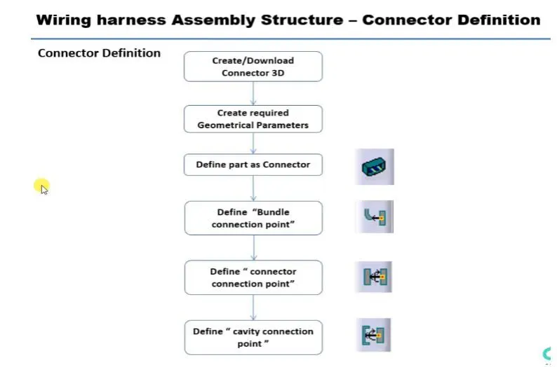
Convecting the Mechanical part design into the Electrical part design for that I followed the below steps
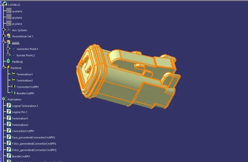
the connector is shown below
part name : c-dt06-2s-a-3d
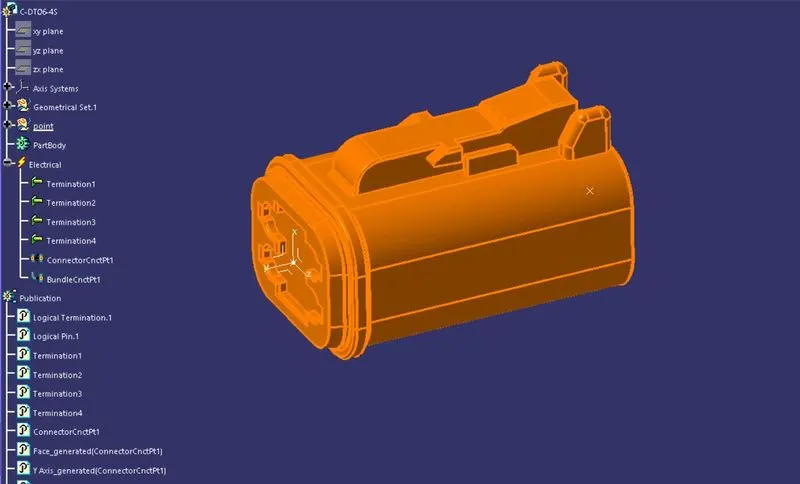
part name : c-dt06-4s-a-3d
part name : c-dt06-6s-a-3d
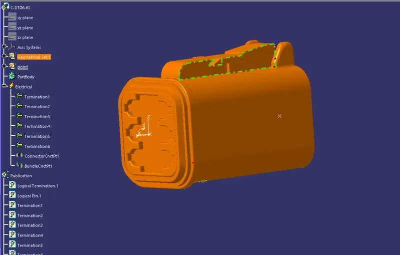
part name : c-dt06-08sa-b-3d
REFERENCE ARE CREATED ON THE FRONT PLACE FOR YOUR EASY ARRANGING THE CONNECTORS IN THE GIVEN LAYOUT
LAYOUT IS CREATED NOW WE GOING TO ARRANGE OUR CONNECTOR IN AN GIVEN ORDER
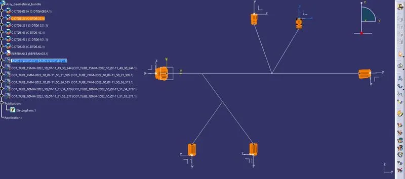
NOW SWITCH TO ELECTRICAL HARDNESS ASSEMBLY AND CREATE THE MULT-BRANCHABLE SEGMENT
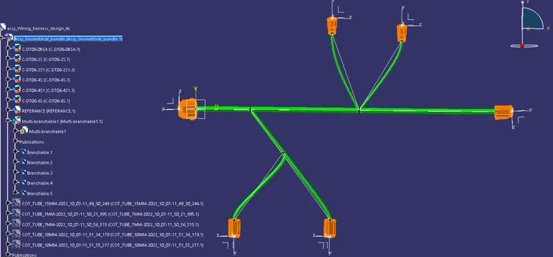
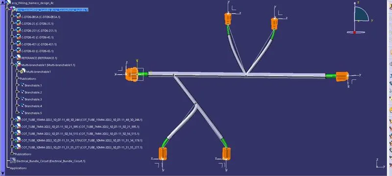
COT-TUBE IS ADDED TO THE PRODUCT FOR EACH AND EVERY BUNDLE FROM HEAT AND FRICTION
MEASUREMENT IS TAKEN FOR YOU AT EACH AND EVERY BRANCH TO CONFIRM
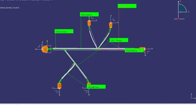
THE FINAL IMAGE IS SHOWN BELOW