Wiring harness design in CATIA V5 - 3D modeling Week 4 Challenge
Task:
Objective:
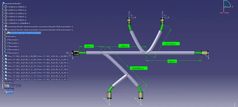
- Route the following harness layout in Electrical workbench. Make assumption for harness bundle diameters. Use Following connectors as shown in layout diagram.
- Add protective covering on all branches connected to DT06-2S & DT06-4S connectors. Keep end extremity at 30mm (from connectors end).
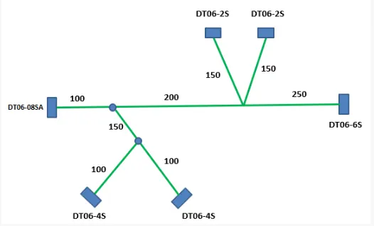
Construction Of Model:
Required Connector Electrically Defined to move on to Wiring Harness Assembly:
- DT06-4S - 2 no.s
- DT06-6S - 1 no.
- DT06-2S - 2 no.s
- DT06-08SA - 1 no.
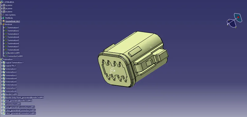
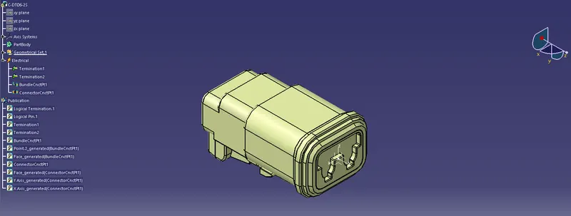
1) DT06-08SA:
1) The Connector Is First Uploaded In The Part Design Workbench.
2) We Define The Points For Connector Connector And Bundle Connection.
3) The Axis Systems Are Placed On The Connector Connection.
4) Then Move on to Electrical Part Design and Define Connector.
5) Then, Connector Connection Point Is Defined.
6) Finally Bundle Connection Point Is Defined.
Model:
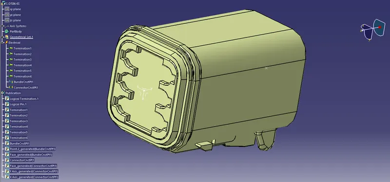
2) DT06-6S
1) The Connector Is First Uploaded In The Part Design Workbench.
2) We Define The Points For Connector Connector And Bundle Connection.
3) The Axis Systems Are Placed On The Connector Connection.
4) Then Move on to Electrical Part Design and Define Connector.
5) Then, Connector Connection Point Is Defined.
6) Finally Bundle Connection Point Is Defined.
Model:
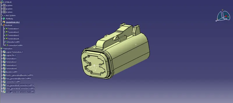
3) DT06-4S:
1) The Connector Is First Uploaded In The Part Design Workbench.
2) We Define The Points For Connector Connector And Bundle Connection.
3) The Axis Systems Are Placed On The Connector Connection.
4) Then Move on to Electrical Part Design and Define Connector.
5) Then, Connector Connection Point Is Defined.
6) Finally Bundle Connection Point Is Defined.
Model:
4) DT06-2S:
1) The Connector Is First Uploaded In The Part Design Workbench.
2) We Define The Points For Connector Connector And Bundle Connection.
3) The Axis Systems Are Placed On The Connector Connection.
4) Then Move on to Electrical Part Design and Define Connector.
5) Then, Connector Connection Point Is Defined.
6) Finally Bundle Connection Point Is Defined.
Model:
Wiring Harness Routing:
Construction Procedure:
Step 1: All the Connectors Required For the Wiring Harness Routing Should Electrically Defined.
Step 2: Inserted Connectors Should Be Positioning As per the Layout Measurement.
Step 3: After Inserting Connectors, the Routing Definition is given to get Multi-Branches between Connectors.
Step 4: Then, Protective Covering are used to cover the Branches with 30mm End Extremity to the Connectors.
Wiring Harness Routing Model:
Conclusion:
The Given harness layout has Been Routed. As Per the Layout Mentioned With Measurements.