Wiring harness design in CATIA V5 - 3D modeling Week 4 Challenge
Week 4-: Wiring Harness Design in Catia V5 & 3D Modelling Challenge
Introduction-: In this challenge we need to define wire harness layout in electrical workbench, by defining the connectors & their assembly as an electrical part & assembly in electrical workbench & then define the wire routing based on the layout provided.
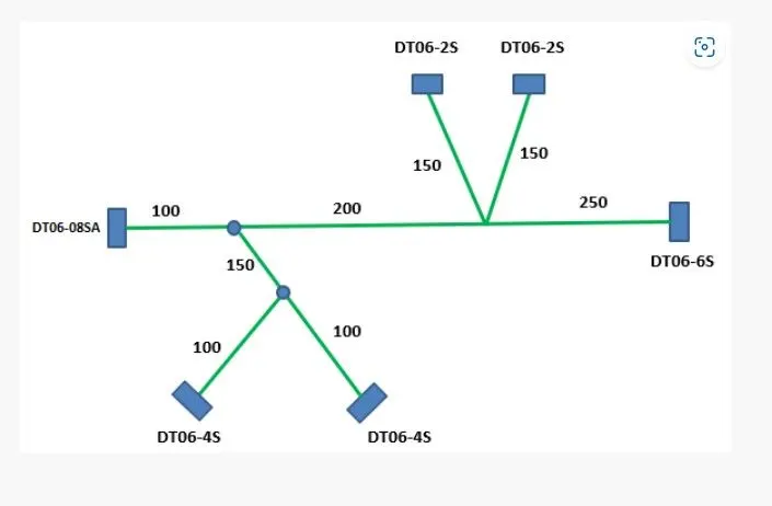
Procedure-:
a. Create Assembly & Define Connectors as an Electrical Part in Assembly-:
1. Open the Catia V5 and start working in the mechanical assembly workbench by adding a product.
2. Now add the components in to the assembly such as connectors and define the connectors as an electrical part in the electrical assembly design.
3. For defining the connectors as an Electrical part you need to define the connector connection point & axis as well as the bundle connection point in Part workbench.
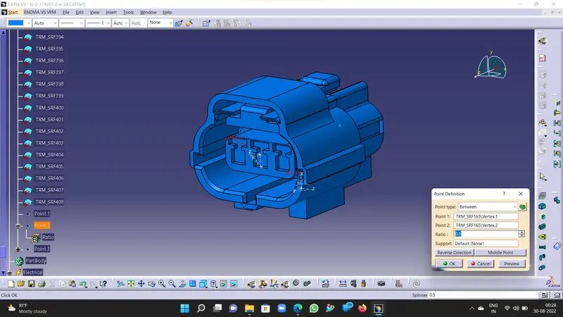
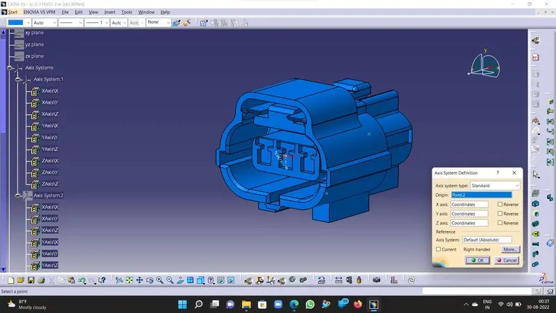
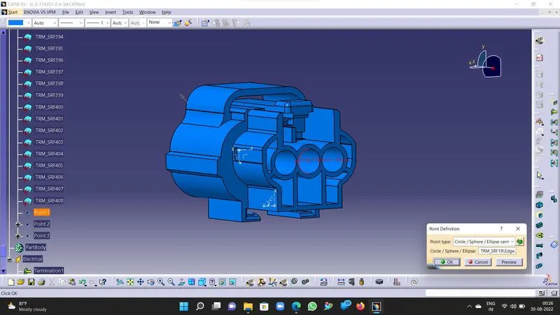
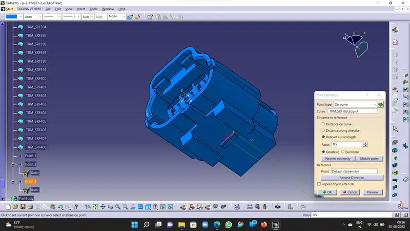
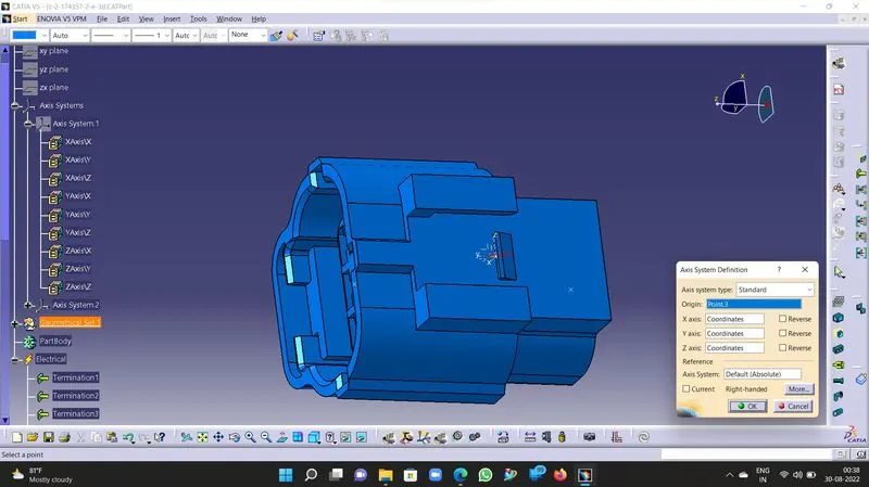
4. Once the points defined switch to electrical assembly and define the connectors as Electrical connectors using "Define Connector" command.
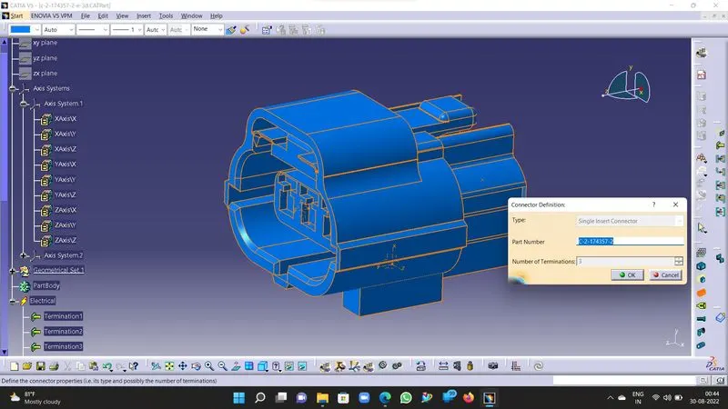
5. Now define the Bundle connection point, Connector connection point & Cavity connection point in the electrical assembly using the appropriate tools as illustrated below.
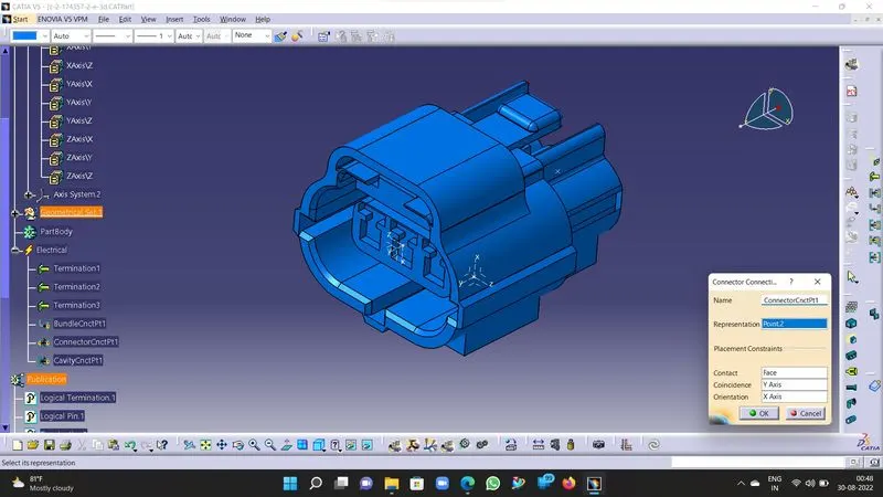
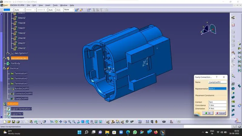
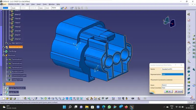
6. Now the Connector is defined as an Electrical part, repeat the steps with each connector in the assembly & save them respectively.
b. Positioning of the Connectors/Components in Assembly-:
1. We can position the components in the assembly by two ways that are-:
- by the help of external references from surrounding data if provided/available.
- by the layout provided or using the tools from mechanical assembly such as Manipulation tools, transformation, smart move, swap etc.
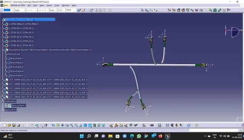
2. We had approached the positioning using the 3D compass and manipulation tools to define the orientation of connectors and position them in required orientation. Illustrated below.
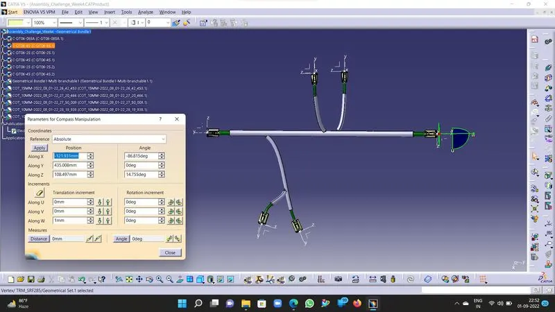
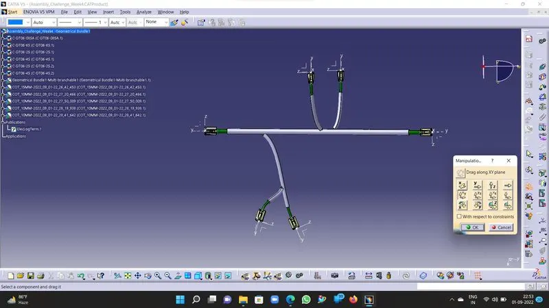
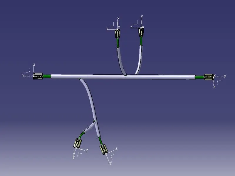
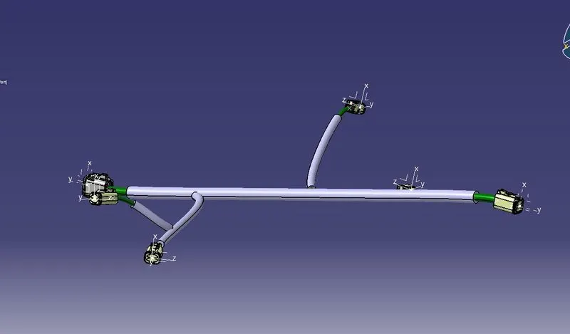
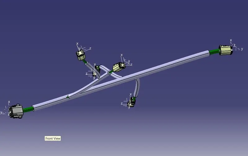
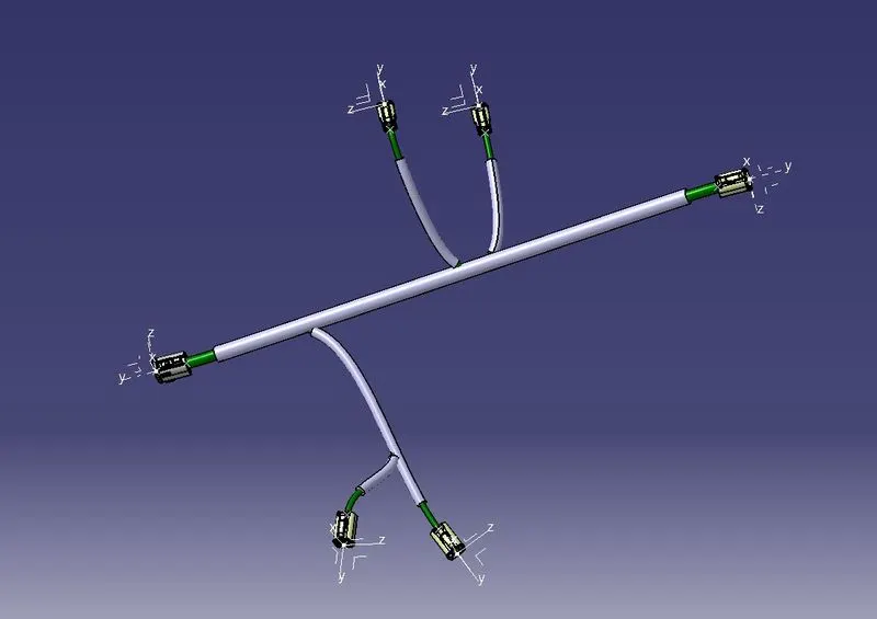
c. Defining of Mechanical Assembly as Electrical Harness Design assembly & wire harness routing , providing protection to routed wire bundles keeping end extremities in mind -:
1. Now switch to Electrical Harness Assembly from mechanical assembly and choose "Geometric Bundle" tool, now choose the product need to be defined as geometric bundle, once choosen it will be defined as Electrical assembly and properties will get stored in publications.
2. Now Define the Multi-Brancheable for the geometric assembly this part file will contain the routing data for the wiring harness.
3. Once the multi-brancheable is defined start routing the wire bundles between electrical connectors by defining the routing paths with the help of branch points, sub-branch etc.
4. Achieve the wire harness routing layout, then exit the multi-brancheable & define the protective coverings for each wire branch using "Define Protective Covering" in Electrical assembly workbench.
5. Once the protective covering is defined, now the wiring harness routing is complete & you can save the assembly in the desired location.
6. Now your Electrical Wiring Harness Design is completed and stored for future reference.
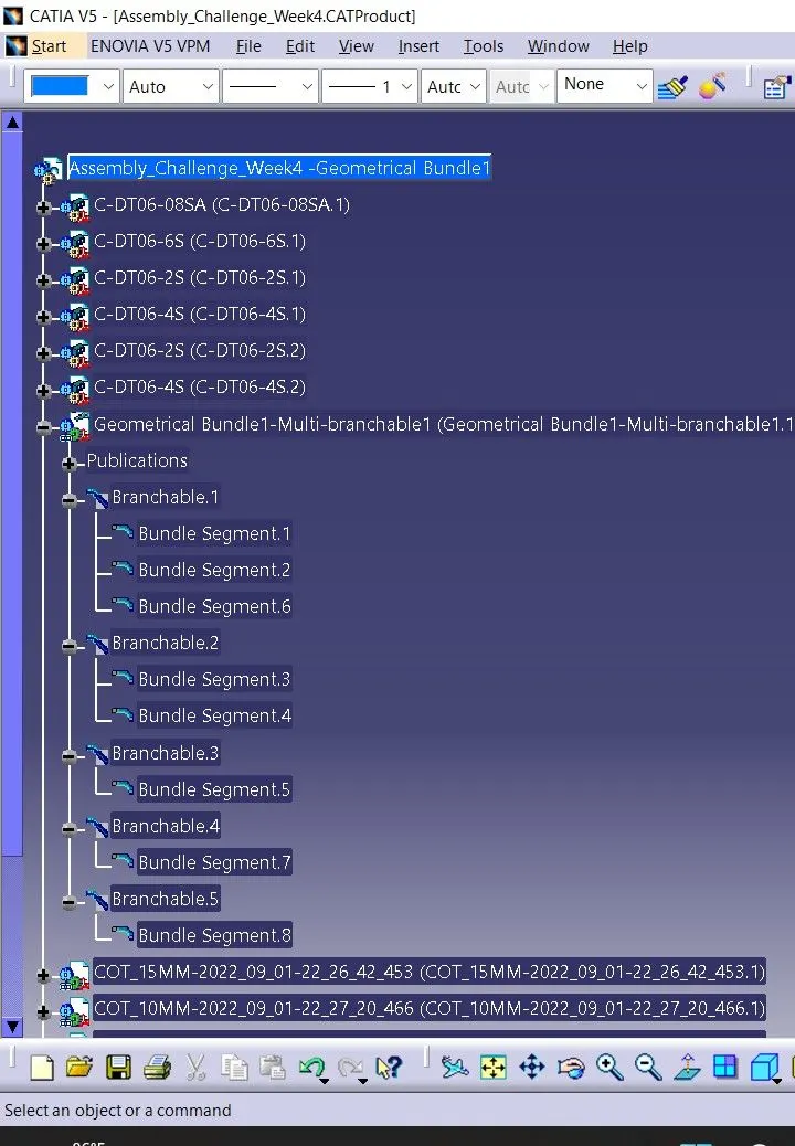
d. Tree Structure for Assembly-:
1. 
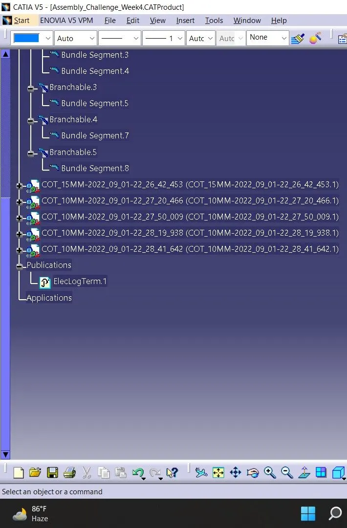
Assembly Views in different orientation-: