Wiring harness design in CATIA V5 - 3D modeling Week 2 Challlenge
Wiring harness design in CATIA V5 - 3D modeling
CONNECTOR MODELING
Download the specified connector from te.com. In the part design workbench provides the center point and axis system to the wire inserting end and connection end. The axis must be given in a specified way:
X-axis: Towards the clamp
Y-axis: Towards the connection
Z-axis: left or right of the connector.
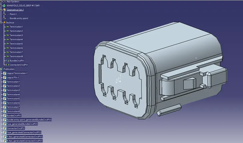
Once the axis is defined. Select the electrical part design workbench. Using the define connector tool, convert the mechanical part into connector. Now given the define connection points and define bundle points. If cavity/mounting is available in the part, define the cavity connection points. Once the electrical properties are given new properties will be shown in the design tree.
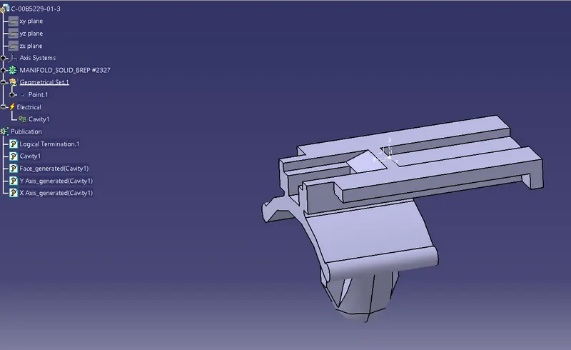
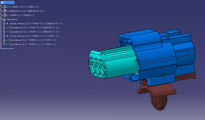
The same process was followed for the second connector.Here we need to include the connector-cavity connection point.This is done to fix the clip on to the connector.The clip has to be defined as a cavity in the electrical part design workbench.
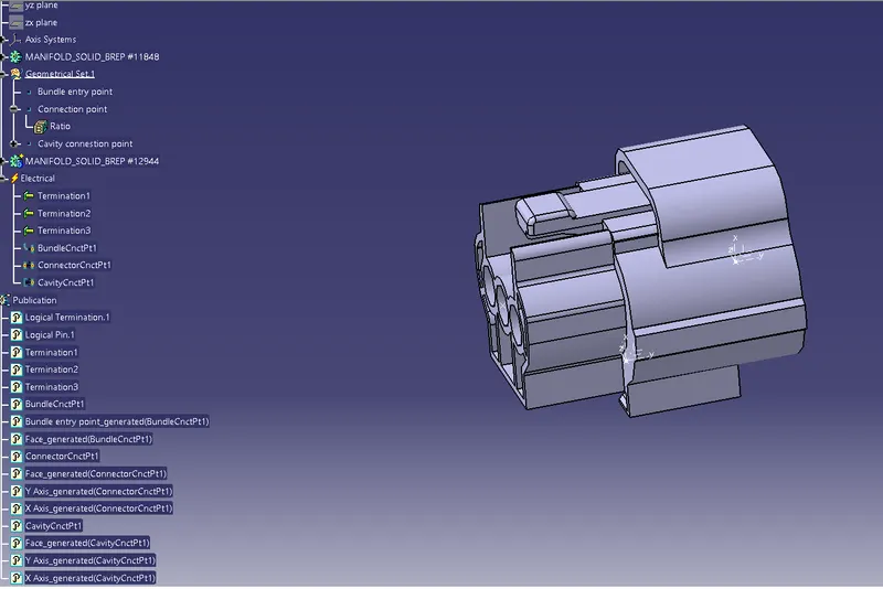
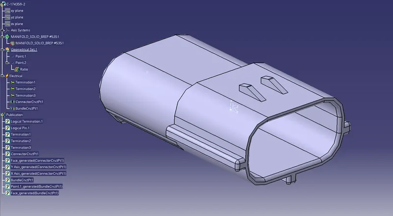
Using the electrical part assembly workbench all the parts can be assembled once the connection points are given.
Conclusion:
The connector is successfully modeled in CATIA V5 and the same is added to the catalog for further references.