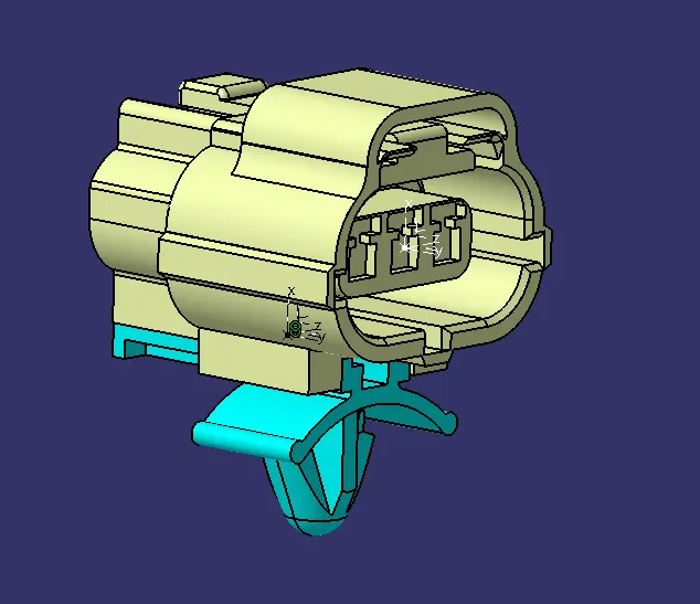
Wiring harness design in CATIA V5 - 3D modeling Week 2 Challlenge
ELECTRICAL CONNECTOR DEFINITION
Introduction:- Electrial assembly design is the major part of Wiring harness where we designs the wiring systems using Catia v5 for the application of routing the connections between vehicle electrical/ electronic systems with the control unit. To make the assembly design possible, we need to define the electrical connectors and their mounting or guiding features in the software. It can be done using Electrical part design workbench in catia.
The 3d data provided for connectors will be a normal model which does not have any definintion for connections in it. An engineer need to define proper connection/mounting points on the structure. The defined parts can be used later as saved catalogues for future assembly purposes.
And after definig the connectors, we can use electrical assembly design to assemble connectors to their respective mounting or guiding features.
Connector definition:
3D model given by: Tyco electronics - TE.com
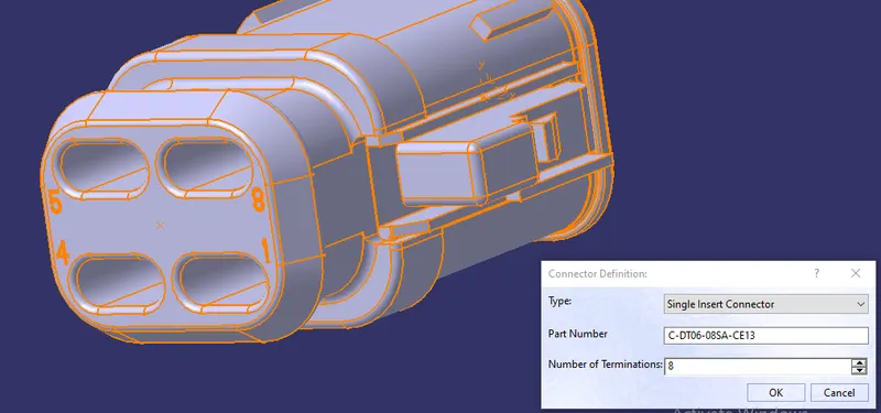
Figure shows a common single insert electrical connector 3d model.
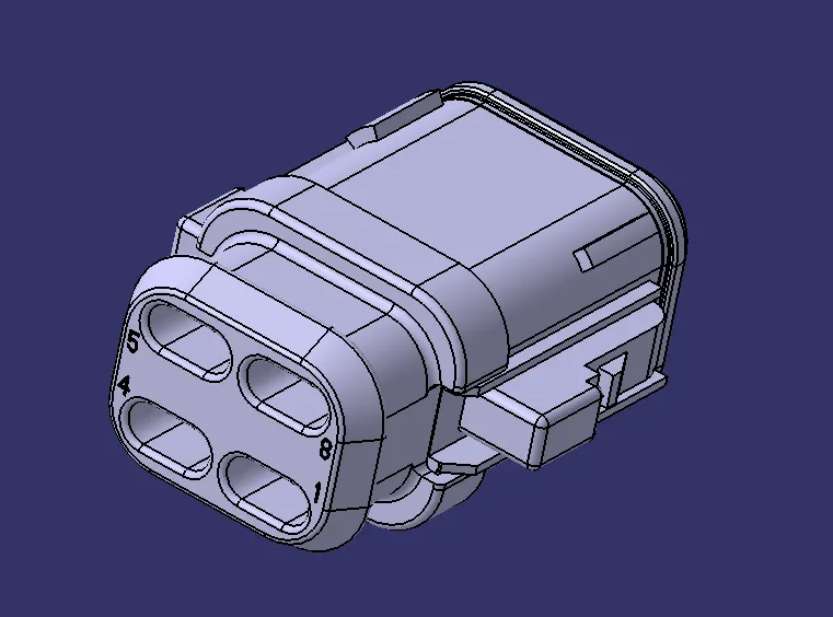
For defining the connection points, we use axis systems.
We have to define axis systems in all the connection/ mounting points according to the position of connection.
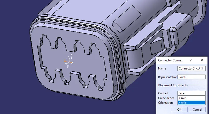
Y axis of axis system is placed along the direction of connection, X axis placed towards the fixing lock orientation.
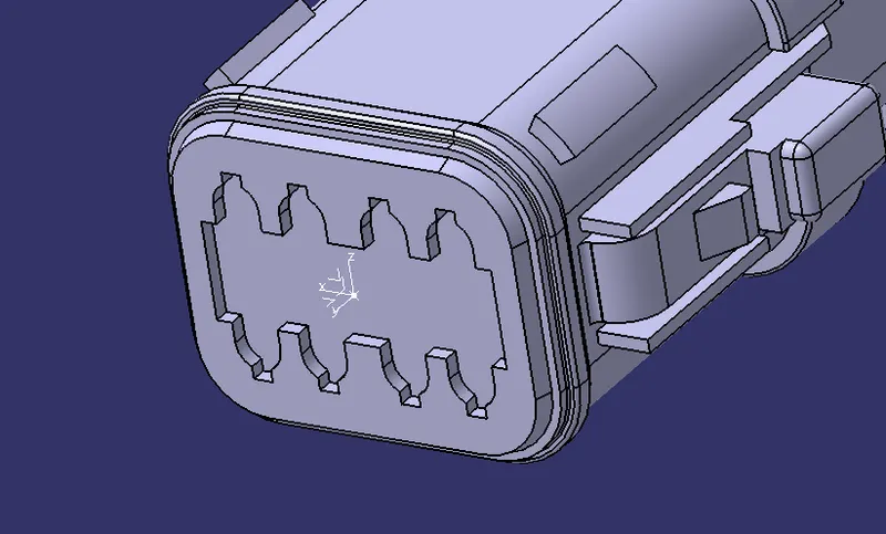
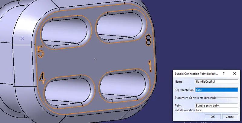
In this speific connector, there is one bundle connection point and another connector connection point as shown. These will be defined separately using electrical part design commands.
Each definitions generated will be shown in the tree structure also as publications.
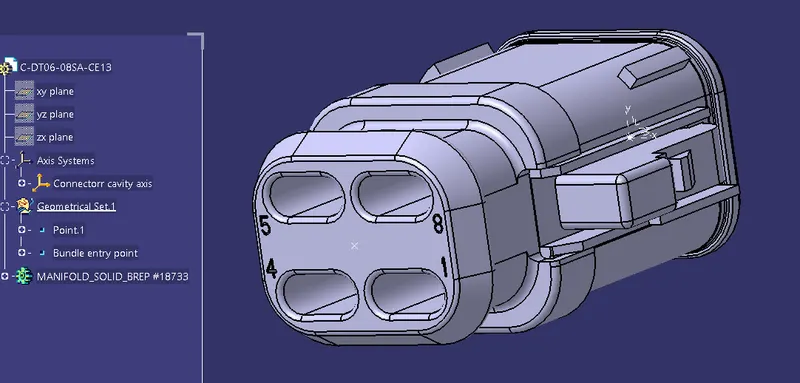
Connector definition:
Bundle Connection point definition:
Connector connection point definition:
Assembly design:-
In this section we see how to make electrical assembly using the Electrical assembly design workbench. The connector and mounting clip initially need to define all connection points and orientation using axis systems.
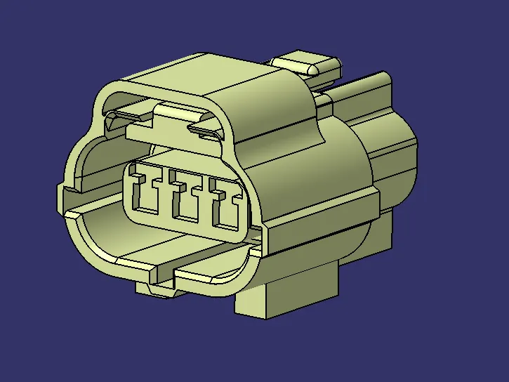
Connection definition:
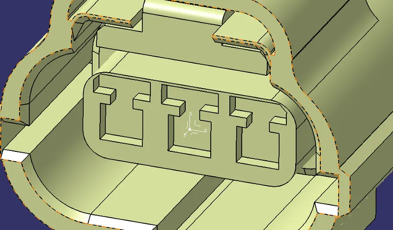
Mating point definition:
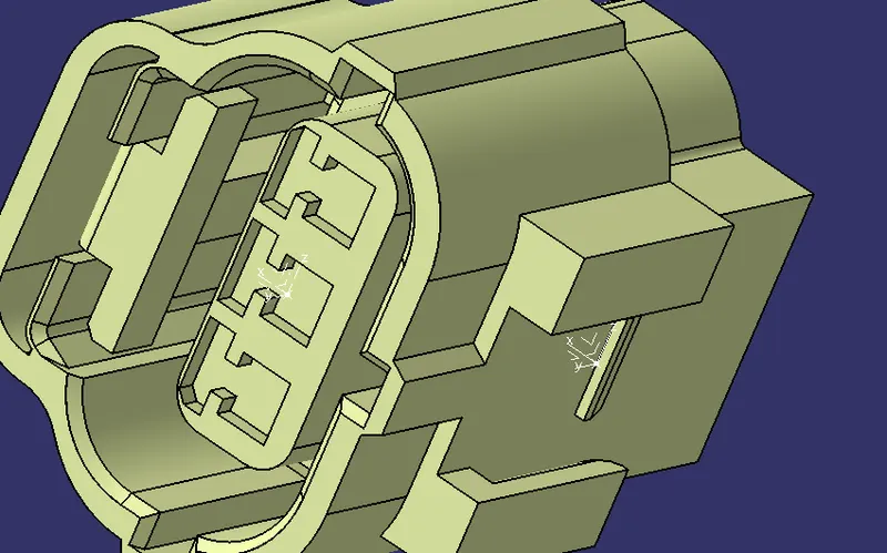
Bundle connection point:
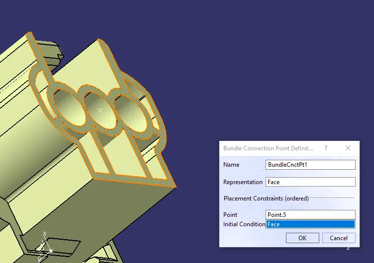
Connector connection point:
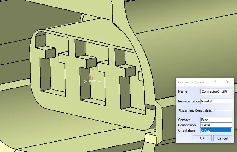
In this case, we need to define the provision for cavity connection also. Face data provided in this defintion is the face which contacts with the mating part.
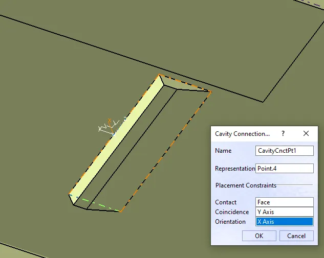
And after this, Define the same mating region in the mounting feature also. The axis system must be made as per the exact orientation which it connects to the connector mating point.
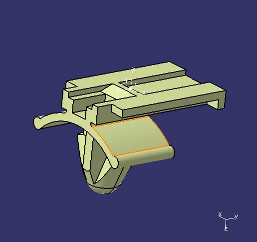
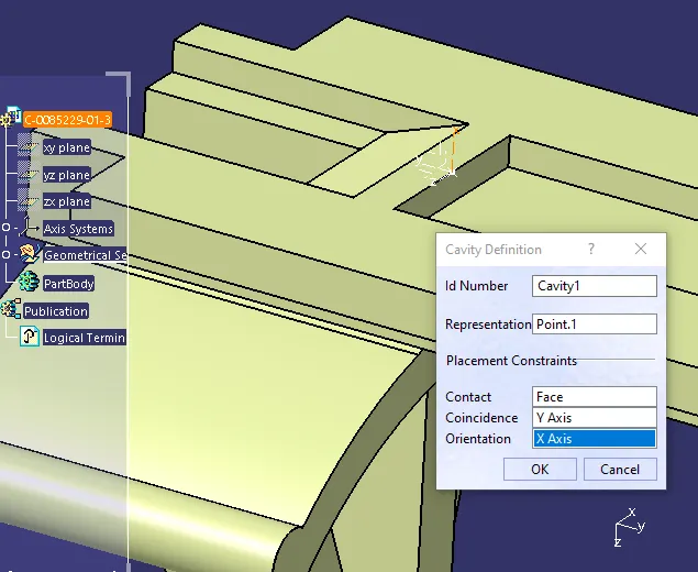
Then define the part as cavity using cavity defeintion tool:
Then we can easily connect them together in the Electrical assembly design workbench using "Connect electrical devices tool".
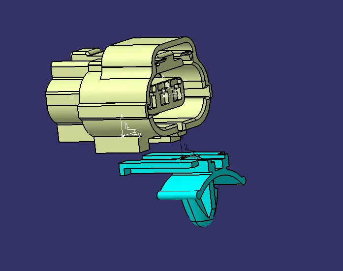
When the tool activates both mating parts, it will show the possible connections. We can select the desired point and the axis to axis constraint will be generated properly as instructed earlier.